
Glyn Hudson and I have been working on a new RFM2Pi board revision, nothing revolutionary, just a small upgrade. The most important features of the board are:
- Atmega328 based, has more memory and hardware serial support
- Runs on the internal 8Mhz oscillator (to save unnecessary components)
- SMT used, board layout is optimized for pick-and-place machine; SMT also means it is lower profile compared to the old version thus more compatible with Raspberry Pi enclosures
- The new RFM2Pi allows programming directly from Raspberry Pi using avrdude (..and OptiBoot)
The board schematics and layout are available on github.
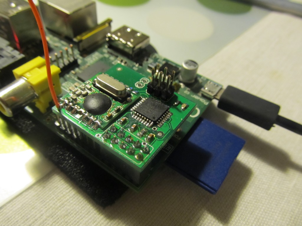
I have few test boards, here is how it looks (this one is hand-built, the solder flux not cleaned yet):
To be able to upload sketches to it, we need OptiBoot installed first. Setting it up is relatively easy (the boards in the shop will come with OptiBoot and the RFM12 demo sketch already installed).
Basically you need a special build for OptiBoot optimized for running on the internal oscillator @ 8Mhz and the optimal for this speed baud rate of 38.4kbps. Excellent work in this setup is described here, let me outline most important steps:
- Add a new build option to OptiBoot’s makefile
# Standard atmega328, only at 38,400 baud for closer clock accuracy AND using 8Mhz internal RC oscillator
#
atmega328_384_8: TARGET = atmega328
atmega328_384_8: MCU_TARGET = atmega328p
atmega328_384_8: CFLAGS += '-DLED_START_FLASHES=3' '-DBAUD_RATE=38400'
atmega328_384_8: AVR_FREQ = 8000000L
atmega328_384_8: LDSECTIONS  = -Wl,--section-start=.text=0x7e00 -Wl,--section-start=.version=0x7ffe
atmega328_384_8: $(PROGRAM)_atmega328_384_8.hex
atmega328_384_8: $(PROGRAM)_atmega328_384_8.lst

atmega328_384_8_isp: atmega328
atmega328_384_8_isp: TARGET = atmega328
atmega328_384_8_isp: MCU_TARGET = atmega328p
# 512 byte boot, SPIEN
atmega328_384_8_isp: HFUSE = DE
# Int. RC Osc. 8MHz, slowly rising power-65ms
atmega328_384_8_isp: LFUSE = E2
# 2.7V brownout
atmega328_384_8_isp: EFUSE = 05
atmega328_384_8_isp: isp
- I also changed pin_defs.h to asjust for the LED pin
#define LED_DDR     DDRB
#define LED_PORT    PORTB
#define LED_PIN     PINB
#define LED         PINB1
- Then run “omake atmega328_384_8” , if you run onto errors, make sure to grab the latest optiboot.c
- Then we need to add a new entry to our arduino-1.0.1\hardware\arduino\boards.txt. Add an entry like this:
##############################################################

atmega328_384_8.name=ATmega328 Optiboot @ 38,400baud w/ 8MHz Int. RC Osc.

atmega328_384_8.upload.protocol=arduino
atmega328_384_8.upload.maximum_size=30720
atmega328_384_8.upload.speed=38400

atmega328_384_8.bootloader.low_fuses=0xE2
atmega328_384_8.bootloader.high_fuses=0xDE
atmega328_384_8.bootloader.extended_fuses=0x05
atmega328_384_8.bootloader.path=optiboot
atmega328_384_8.bootloader.file=optiboot_atmega328_384_8.hex
atmega328_384_8.bootloader.unlock_bits=0x3F
atmega328_384_8.bootloader.lock_bits=0x0F

atmega328_384_8.build.mcu=atmega328p
atmega328_384_8.build.f_cpu=8000000L
atmega328_384_8.build.core=arduino
atmega328_384_8.build.variant=standard
So with these settings in, I was able to upload the modified OptiBoot using my usbtiny ISP programmer.
I have included a pre-compiled OptiBoot in my github repo.
Next, I plugged the board onto my Raspberry Pi. There is a problem in using avrdude directly, there is a good write up about the issue here, but JCW uses a custom tcl script to upload sketches which he didn’t share. The problem is basically to reset the board at the right time and therfore invoke the bootloader so that avrdude can start talking to it. I researched on the available options to work around the issue and found an elegant 2 minute solution by Dean Mao. Basically he uses strace to determine the exact moment when avrdude wants to reset the target board and uses a small python script to perform the reset. The fix is applied as follows:
- Make sure you have python installed on your Pi:
sudo apt-get update
sudo apt-get install python-dev&&python-rpi.gpio
- Grab the modified code for the RFM2Pi board from my repo and apply the fix:
cp autoreset /usr/bin
cp avrdude-autoreset /usr/bin
mv /usr/bin/avrdude /usr/bin/avrdude-original
ln -s /usr/bin/avrdude-autoreset /usr/bin/avrdude
With these fixes applied, I was able to use avrdude and upload the RFDemo sketch directly from RaspberryPi:
avrdude -v -c arduino -p ATMEGA328P -P /dev/ttyAMA0 -b 38400 -U flash:w:RF12_Demo_atmega328.cpp.hex
Neat 🙂
[update] The board is now available for sale in the shop
Hi Martin, greetings from the US. I’ve been following your RFM2Pi, and not having a tiny84 at hand, I already built one using a Mega328 with a resonator, since I already had that and didn’t need to modify Optiboot (laziness kicked in). I have my Pi set up with an expansion cable to a breadboard and the RFM2Pi on the breadboard, and the setup works quite well for the test phase of my build. I do intend to create a board to mount on the header as soon as I complete the tests. I wanted to stay at 16MHz so I can try to push the serial to 115200, the default console rate.
I have the Pi feeding data to emoncms.org and wish to have the Pi furnish time data to the GLCD. I saw the series of posts on doing this, but the php script has changed since the posts, and I am unsure what needs to go where in the raspberrypi_run.php script. I could use a wee bit of help on that if you don’t mind. I would think that should be incorporated in a future release of the _run script. So what if the RFM2Pi sends time and nobody is there to hear it.
Regards,
Hi,
The appropriate place to insert that fragment wold be right after the script inserts the received data i.e. after this line:
// Run the input processor (new to call new version of the input processor..)
new_process_inputs($userid,$inputs);
I’d also implement a timer so that time is sent at most once a minute, not upon each post to emoncms.
if (time()-$todtimer>60)
{
$todtimer = time();
…send time
}
I also think that should be merged in to the code, please do issue a pull request when you manage it
Hi Martin, I’ve made the changes you recommended and by the gods it works! Thanks for the pointer. In case someone else needs this, here is a Cliff’s Notes version of what I did…
Open Terminal and log in as pi, then
cd /var/www/emoncms/Modules/raspberrypi
sudo nano raspberrypi_run.php
Look for these 2 lines (@195/196 on 25Feb13)…
// Run the input processor (new to call new version of the input processor..)
new_process_inputs($userid,$inputs);
Then add this chunk below those two lines …
if (time()-$todtimer>60)
{
$todtimer = time();
$hour = date(‘H’);
$min = date(‘i’);
fprintf($f,$hour.”,00,”.$min.”,00,s”);
sleep(1);
}
Do the CTRL-X,Y,[ENTER] thing, then restart mysql …
sudo /etc/init.d/mysql restart
Then in HomeEnergyMonitor in loop() in the time updating section change rf12_data[1] to rf12_data[0] like so…
if (node_id == 1 || node_id == 2) // for me, node 1 = nanode, node 2 = pi, set to your system nodes
{
digitalWrite(greenLED, HIGH); // flash the LED to indicate the time is updated
while( rf12_data[0] > 23) // fixes the hour when returned from emoncms,
{ // which returns GMT which results in a negative
rf12_data[0] += 24; // number from 1800 to midnight in US CTZ
} // which the rtc can’t understand.
RTC.adjust(DateTime(2013, 2, 25, rf12_data[0], rf12_data[2], rf12_data[3]));
last_emonbase = millis();
delay(25);
digitalWrite(greenLED, LOW);
}
Hi guys.
Following the discussion here [1] about raspberry_run.php, I’m working on a python rewrite of the RFM2Pi gateway [2]. It is working, already, though it stills needs a little bit of work (hardcoded parameters) before asking for integration.
This time feature seems like an easy one. I can even make it optional.
I don’t have the emonGLCD to test it, though. Can you please clarify or point me to an explanation of the time format ?
The php code here :
$hour = date(‘H’);
$min = date(‘i’);
fprintf($f,$hour.”,00,”.$min.”,00,s”);
yields
09,00,57,00,s
Is this correct ?
Congratulations Martin for the new board !
[1] https://github.com/emoncms/raspberrypi/issues/5
[2] https://github.com/Jerome-github/emoncms_raspberrypi/blob/raspberrypi_run_python_script/rfm2pigateway.py
Jerome,
some impressive work you have done 🙂
Yes, this is the string we need to pass to the RFM2Pi board in order to have it send out time.
Cheers,
Martin
Thank you Martin.
I am using a “RFM12Pi Raspberry Pi Expansion board kit (433 Mhz)”, pre-loaded with your software. which I understand is this sketch :
https://github.com/mharizanov/RFM2Pi/blob/master/firmware/RFM2Pi_RF12_Demo/TinySensor_RF12_Demo/TinySensor_RF12_Demo.ino
Here’s what I get on the serial port :
2013-03-02 19:22:04,282 INFO Serial RX: 10 182 6
(node 10, temperature)
2013-03-02 19:00:54,584 INFO Serial RX: > 15i
2013-03-02 19:00:54,589 INFO Serial RX: > 4b
2013-03-02 19:00:54,594 INFO Serial RX: > 210g
(apparently the board repeats on the serial link what I just sent it, as an acknowledgement I guess)
Now, when I try to send “09,00,57,00,s”, for instance
ser.write(“09,00,57,00,s”)
I get
2013-03-02 19:24:05,003 INFO Serial RX: > 0s
2013-03-02 19:24:05,009 INFO Serial RX: -> 4 b
Is this normal behaviour ? Could I be doing anything wrong ?
Is there a page that lists all the inputs I can expect from the serial port ?
Thanks.
For anyone reading those comments, I’m afraid there was an error here.
It should be
fprintf($f,"00,".$hour.”,”.$min.”,00,s”);instead of
fprintf($f,$hour.”,00,”.$min.”,00,s”);This would be Trystan’s php implementation : https://github.com/emoncms/raspberrypi/blob/master/raspberrypi_run.php#L313
See here for the bug report : https://github.com/Jerome-github/oem_gateway/issues/3#issuecomment-23677558
Perhaps Martin can confirm this.
Hi, the output looks normal, it acknowledges that it sent 4 bytes so you see the “4b”
Browse the code to see how it works, basically is is a simplified version of JCW’s RF12Demo sketch https://github.com/jcw/jeelib/tree/master/examples/RF12/RF12demo
It seems to have better documentation, however the version I use is stripped down of much functionality to fit the Attiny84 8K limit. You can safely ignore lines starting with “>” in your code, these are just info messages. I assume you have sen the way emoncms handles this in PHP https://github.com/emoncms/raspberrypi/blob/master/raspberrypi_run.php
Yes, I used raspberry_run.php as an example.
I do trash the > messages, but here, I’m receiving “->” (see the minus sign).
2013-03-02 19:46:12,880 INFO Serial RX: > 0s
2013-03-02 19:46:12,885 INFO Serial RX: -> 4 b
From your answer, I would expect something like :
2013-03-02 19:46:12,885 INFO Serial RX: > 4 b
I’ll read your link. Thanks.
Ah, yes it is actually a ” ->”, note the leading space
Since the original raspberry_pi.run doesn’t do time sends, it has no handling of this case. You can then just add a rule to ignore lines starting with ” ” and “>” 🙂
Ah, ok then.
First I strip of blank spaces to get something like [’10’, ‘132’, ‘123’] or [‘->’, ‘4’, ‘b’].
Then, I discard all frames beginning with either ‘>’ or ‘->’ as information messages.
And I’m logging a warning if
– number of elements is not odd and at least 3
– all elements are not integers
I still don’t understand the “> 0s” I receive.
I read the page you pointed me to :
https://github.com/jcw/jeelib/tree/master/examples/RF12/RF12demo
It is not a comprehensive description of the dialog format, more like a startup tutorial, and I didn’t spend much time in the code, I must admit.
It says
10. In the above test, you’re sending packets with no actual data other than
what the protocol itself requires to function properly. To include some test
data use “1,2,3,0s” or “1,2,3,0a” with “1,2,3” being the actual data. This
sends a test packet with 3 data bytes (you can send up to 66 data bytes).
The “t” commands is available as shorthand for “0,1,2,…,63,64,65,0a”.
Should we send “09,00,57,00s” instead of “09,00,57,00,s” ?
Anyway, from my (receiver) side it seems to work. At least the program does not crash on unhandled RX frames. I don’t have any emonGLCD to test.
I commited the change to my fork :
https://github.com/Jerome-github/emoncms_raspberrypi/commit/a75c2b54aae42698d492f9a1c4921084d3a4626a
There seems to be another case I don’t manage : the help message…
At least it is interpreted as a misformed message, but the script does not crash.
2013-03-12 11:09:47,516 INFO Serial RX:
2013-03-12 11:09:47,519 WARNING Misformed RX frame: [”]
2013-03-12 11:09:48,628 INFO Serial RX: Available commands:
2013-03-12 11:09:48,631 WARNING Misformed RX frame: [‘Available’, ‘commands:’]
2013-03-12 11:09:49,753 INFO Serial RX: 123 x – Toggle configuration change protection, 1=Unlocked
2013-03-12 11:09:49,757 WARNING Misformed RX frame: [‘123’, ‘x’, ”, ”, ”, ”, ”, ‘-‘, ‘Toggle’, ‘configuration’, ‘change’, ‘protection,’, ‘1=Unlocked’]
2013-03-12 11:09:50,880 INFO Serial RX: i – set node ID (standard node ids are 1..26)
2013-03-12 11:09:50,883 WARNING Misformed RX frame: [”, ‘i’, ”, ”, ”, ”, ‘-‘, ‘set’, ‘node’, ‘ID’, ‘(standard’, ‘node’, ‘ids’, ‘are’, ‘1..26)’]
2013-03-12 11:09:52,181 INFO Serial RX: b – set MHz band (4 = 433, 8 = 868, 9 = 915)
2013-03-12 11:09:52,184 WARNING Misformed RX frame: [”, ‘b’, ”, ”, ”, ”, ”, ‘-‘, ‘set’, ‘MHz’, ‘band’, ‘(4’, ‘=’, ‘433,’, ‘8’, ‘=’, ‘868,’, ‘9’, ‘=’, ‘915)’]
2013-03-12 11:09:53,309 INFO Serial RX: g – set network group (RFM12 only allows 212, 0 = any)
2013-03-12 11:09:53,312 WARNING Misformed RX frame: [”, ‘g’, ”, ”, ”, ‘-‘, ‘set’, ‘network’, ‘group’, ‘(RFM12’, ‘only’, ‘allows’, ‘212,’, ‘0’, ‘=’, ‘any)’]
2013-03-12 11:09:54,426 INFO Serial RX: c – set collect mode (advanced, normally 0)
2013-03-12 11:09:54,430 WARNING Misformed RX frame: [”, ‘c’, ”, ”, ”, ”, ”, ‘-‘, ‘set’, ‘collect’, ‘mode’, ‘(advanced,’, ‘normally’, ‘0)’]
2013-03-12 11:09:55,549 INFO Serial RX: …, a – send data packet to node , with ack
2013-03-12 11:09:55,553 WARNING Misformed RX frame: [‘…,’, ‘a’, ‘-‘, ‘send’, ‘data’, ‘packet’, ‘to’, ‘node’, ‘,’, ‘with’, ‘ack’]
2013-03-12 11:09:56,672 INFO Serial RX: …, s – send data packet to node , no ack
2013-03-12 11:09:56,676 WARNING Misformed RX frame: [‘…,’, ‘s’, ‘-‘, ‘send’, ‘data’, ‘packet’, ‘to’, ‘node’, ‘,’, ‘no’, ‘ack’]
2013-03-12 11:09:57,798 INFO Serial RX: l – turn activity LED on DIG8 on or off
2013-03-12 11:09:57,801 WARNING Misformed RX frame: [”, ‘l’, ”, ”, ”, ”, ”, ‘-‘, ‘turn’, ‘activity’, ‘LED’, ‘on’, ‘DIG8’, ‘on’, ‘or’, ‘off’]
2013-03-12 11:09:58,912 INFO Serial RX: Current configuration:
2013-03-12 11:09:58,915 WARNING Misformed RX frame: [‘Current’, ‘configuration:’]
2013-03-12 11:10:00,033 INFO Serial RX: 79 i15 g210 @ 433 MHz Lock: 1
2013-03-12 11:10:00,037 WARNING Misformed RX frame: [’79’, ‘i15’, ‘g210’, ‘@’, ‘433’, ‘MHz’, ”, ‘Lock:’, ‘1’]
Pingback: Funky v2 as RFM12B to Raspberry Pi gateway | Martin's corner on the web
Pingback: TCP/IP over RFM12B and Raspberry Pi as gateway | Martin's corner on the web
Pingback: Dirt Cheap Low Power Wireless Sensor Node using nRF24L01+ 2.4GHz | Martin's corner on the web
Inspired by your post I managed to create a rfm12pi board with an ATMEGA8 running at 16MHz.
Thanks for the great posts
Hi,
I’m in the process of building a home monitoring network. I really like your work, but how much does it differ from using a JeeNode connected to a Raspberry Pi like this post: http://jeelabs.org/2012/09/20/serial-hookup-jeenode-to-raspberry-pi/
Will I be able to use the JeeNode and load it with the same code to interface with emoncms, reading data from another JeeNode?
It will absolutely work, go ahead and try it out
Hi all,
Is there a PDF file of the schematic available ?? Esp. I want to know which pins of the GPIO connector are used.
Thanks
Rudi
Pingback: Martin's corner on the web
Hi Martin!
Great work, thank you!
Just a question about the design: why did you choose to use a microcontroller instead of connection the RFM12b module directly to the SPI interface of the raspberry pi? …seen here for example: http://www.seegel-systeme.de/index.php?page=funksensoren-am-raspberry-pi (sorry, in German)
…just curious about your thoughts! 🙂
Hi,
At that time someone was blogging that direct RFM12B SPI connection with the Raspberry Pi caused him significant headaches because of the small buffer that the RFM12B has. That may have changed with more recent kernel versions. Delegating the task to a micro controller made this so much easier. Probably worth re-visiting this option now again, thanks for the heads up!
Thanks!
…still wondering what might be the best option for me – whether the “extra layer” with the micro controller makes it better or worse… 😉
Well, anyway, we’ll see – maybe, I should just pick one option and give it a try!
Pingback: NodeRED RFM2Pi to emonCMS gateway | Martin's corner on the web
Hi Martin,
I had some Arduino mini laying around so I designed a board similar to yours using the mini instead of the ATMega chip. The advantage is that all free pins of the mini are still useable. Feel free to point your readers to my blog http://glaskugelsehen.wordpress.com/2014/05/01/raspberry-pi-empfangt-auf-868-mhz/
Regards
Reinhard
Hi Martin,
I built a board similar to your RFM12Pi board in order to learn basic PCB design and I also used the internal oscillator of the AVR. That did however not work at all, the AVR would hear the RasPi but not the other way around. Checking the raw UART traffic on a logic analyser revealed that the AVR transmitted at about 59kbaud (when set to 57200!) which I interpreted as the internal osc being completely out of whack. Adding an external crystal and saved the day. I noted a comment in raspberrypi_run.php saying that the data out from the RFM2Pi sometimes accidentally changes settings and that the cause might be data corruption. Could using the internal oscillator be the culprit here also?
Cheers,
Johan
Interesting,
I haven’t had such case yet, although it totally makes sense. I have tried out internal oscillator calibration on Attinys before, but not on Atmega. Google for it, it uses the UART to adjust OSCCAL http://forum.arduino.cc/index.php/topic,8553.0.html . Could work on Atmega328 with some code adjustment.
The settings change was another thing (software UART), it was resolved in the v2 of the board by using Atmega328’s hardware uart
Cheers
Pingback: Interfacing with Paradox home security system attempt 2 | Martin's corner on the web
Pingback: DIY Internet of Things Fire Alarm | Martin's corner on the web
Pingback: MQTT topic tree structure improvements | Martin's corner on the web