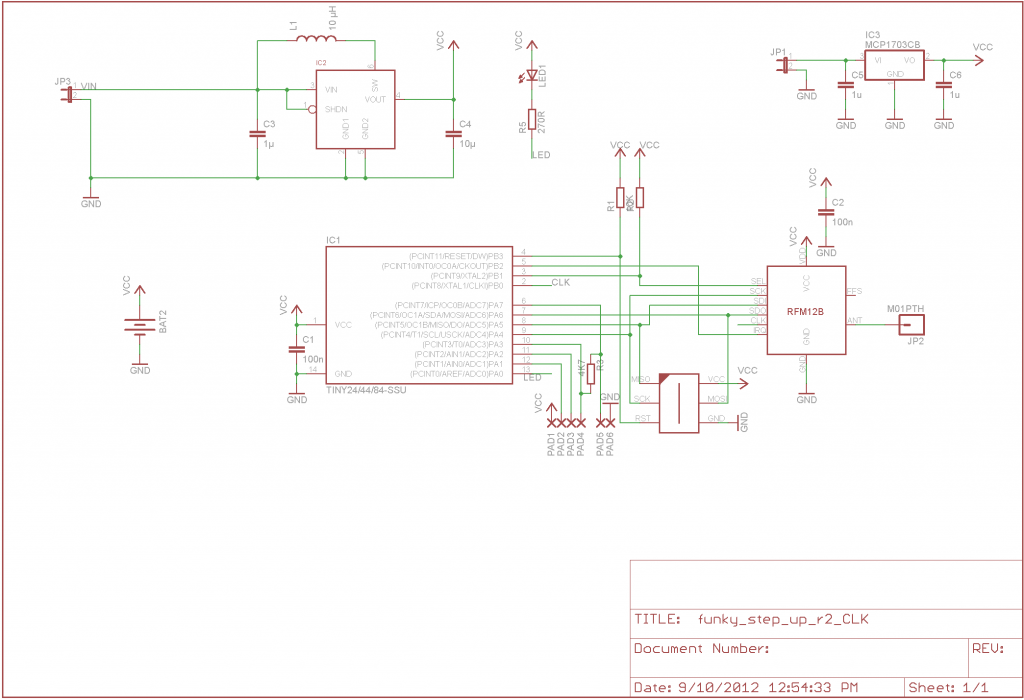
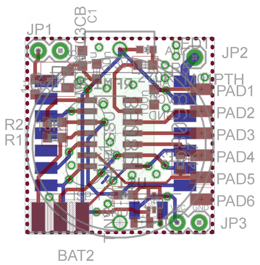
Tobias’s original ‘Funky’ had voltage regulator, that I removed in my version in favor of a voltage step-up circuit. How about having both on the Funky and you will decide which one to use depending on the concrete application? Well, I managed to squeeze in a voltage regulator, while keeping the step-up circuit. Another change that I made is that I connected the CLK output from the RFM12B module to the ATTiny84’s CLKI, so I can test if I can run it off the RFM’s 10Mhz crystal. Here is how it worked out:
I will order few test PCBs and see how it works.


Pingback: Using Nanode RF and WiNode for Server driven control | Nanode
Hi Martin,
Thank you for all your blogs. They are just what I have been looking for.
I would like to begin with a Funky board. Which would you recommend as stable version? SuperFunky looks attractive but you possibly have not tested it yet – and I don’t see a link to the Eagle files.
I also intend building the RFM2Pi – again, would you recommend the Tiny84 or the 328 for a starter?
Regards,
Mike Alport
Mike,
the SuperFunky (in this particular design) was a concept that never made it into the physical world,
see the final V1 here http://harizanov.com/wiki/wiki-home/funky/
I later decided to go for a Atmega32u4 see http://harizanov.com/wiki/wiki-home/funky-sensor-v2/
Regarding RFM2Pi – I’d go for Atmega328 running on the internal oscillator. See my posts about RFM2Pi v2. You can build one on a breadboard for 20 minutes using the schematics provided and jumper wires. The RFM12b can easily be made breadboard friendly too – see http://jeelabs.net/boards/6/topics/1012