
[This project is obsoleted and not supported]
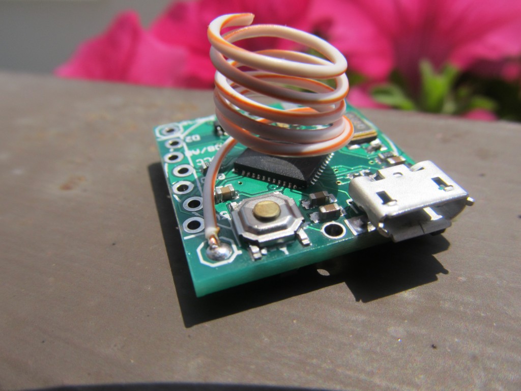
The “Funky v2” is a miniature open source/hardware cut-down clone of the Arduino Leonardo with RFM12B radio module. It is intended as low power, battery operated remote sensing node with USB interface. Due to the miniature size, only few carefully selected pins are available at the side header, none the less that is more than sufficient to interface several sensors at a time.
Having gained experience with my Funky v1 project, I decided to create a new version. The Funky v1 project is a success, yet the areas I wanted to optimize are:
- The Attiny84 MCU that was used in the Funky v1 has limited RAM and sketch memory
- The Attiny84 requires an ISP programmer for sketch uploading
- The Attiny84 required a modified Arduino core
- Many of the available Arduino libraries are not compatible with Attiny84
So the Funky v2 was created, see my posts here , here and here
- Board size is 20×21.2mm (0.78″x0.83″) in size (same as Funky v1)
- The MCU used in an Atmega32U4, the same MCU that Arduino Leonardo uses. This makes the Funky v2 a minuature Arduino Leonardo compatible board with RFM12b transciever module
- The Funky v2 has the Caterina bootloader, so programming is done with Arduino IDE via micro USB cable
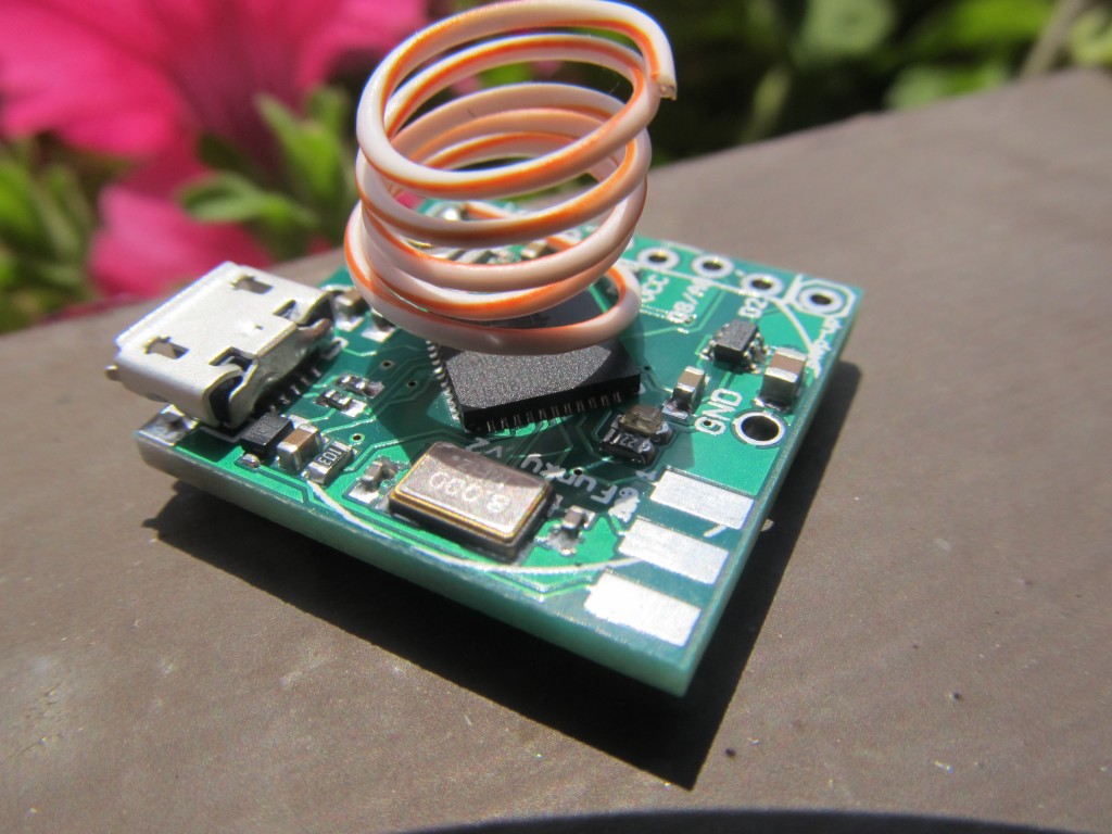
- Uses external 8Mhz crystal (can switch to internal RC clock in software as described here)
- Operates on 3.3V
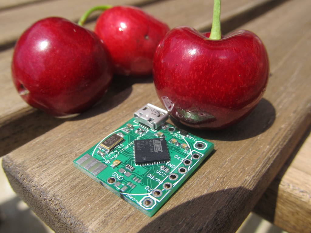
- Weights only 3 grams
Funky v2 is available for sale in limited quantities in the shop.
Eagle design files and example sketches are available on my github repository.
Some of my projects involving Funky v2:
- Wearable wireless body temperature logger/monitor with DS18B20
- OLED status display
- Flood alarm
- RGB LED project
- Temperature sensor node
- Weight logger
- Frequency generator
- Using in energy harvesting project
- Soil moisture wireless node
- April fool prank
- Software I2C with Funky v2
- TCP/IP over RFM12b serial connection
- Frequency counter
- RFM12b gateway to emoncms
- Controlling RF power sockets
- IR receiver
- DHT22
- Pulse counting
Complete list of examples: https://github.com/mharizanov/new_Funky/tree/master/examples
Funky v2 revision 2 schematic/board layout:
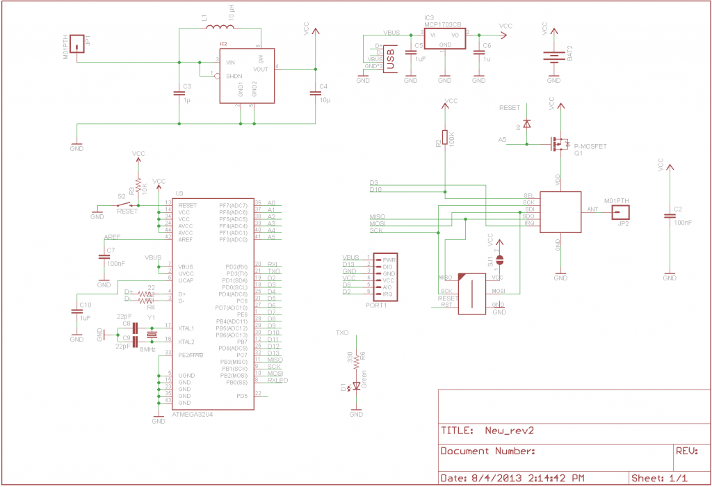
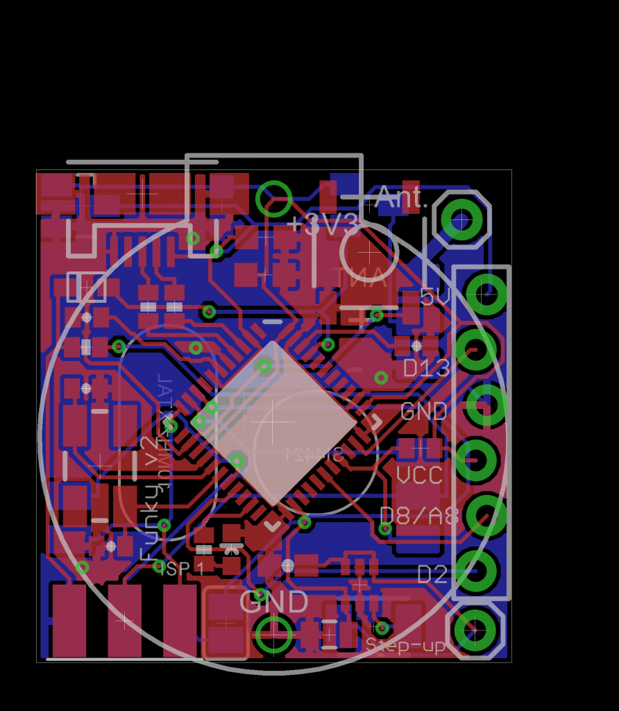
Note the added MOSFET to control the RFM12B’s power state; This requires explicitly powering up RFM12B transciever before initialization:
pinMode(A5,OUTPUT); // RFM12B power control pin9
digitalWrite(A5,LOW); //Make sure the RFM12B is on (LOW is on)
delay(20); // Allow for RFM12B to start
....RFM12B initalization code here.......
Setting up Arduino IDE for the board
Funky v2 r2 will have the Caterina bootloader and will identify itself as an Arduino LilyPad USB. The purpose of this is to have Arduino IDE support for the Funky v2 without the need of any additional setup. Both Arduno LilyPad USB and Funky v2 operate on 3.3V @ 8Mhz, so it is important to select that board type and not the Arduino Leonardo that runs on 16Mhz. Simply plug in the Funky v2 and when asked for drivers (Windows), navigate to the Arduino/drivers folder.
Older Funky v2 revisions need to use the Arduino Fiov3 drivers. The ZIP file includes instructions on using them.
Powering the board
Note: The micro-USB connector is soldered on the board — not through it. Be gentle when plugging and unplugging your USB cable.
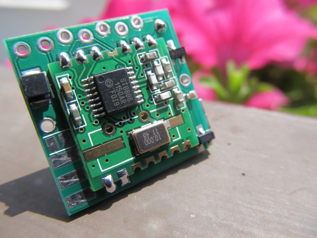
The board can be powered from the micro USB plug and will regulate that input to 3.3V using the the Torex XC6206 LDO regulator included on the board (Funky v2 used MCP1700 LDO prior to Aug 14th 2013, see my post here) . The VUSB line is exposed as a pin on the side header, meaning that you can power the board from there too, just do not exceed the 6V limit that the ATMega32U4 VUSB has. The XC6206 dropout voltage according to the datasheets is 250mV meaning the minimum supply voltage when powering via the VUSB should be 3.3V+0.25=3.55V, so LiPo batteries can be also used as well.
The board carries an option for the LTC3525ESC6 (3 or 3.3V versions) boost regulator and supporting elements to be included, this is useful when you wish to power the board from a 0.8 – 5.5V source and get that regulated to 3.3V. I use that option to power the Funky v2 from a single AAA battery.
The board can also be powered from a single CR2032 battery, but unlike the Funky v1 the battery holder now can only be soldered at the side where the RFM12B module lays as the micro USB connector stands on the way on the reverse side. See example of this setup here.
Running on battery is one one of the advantages of the Funky v2 project, however it needs taking special care to reduce power usage and therefore prolong battery life. Using this example sketch I managed to bring the power consumption down to 0.02mA @ 3V in sleep mode.
NOTE: Please remove any battery attached when plugging into USB.
The default fuse settings I use are the same as Arduino LilyPad USB:
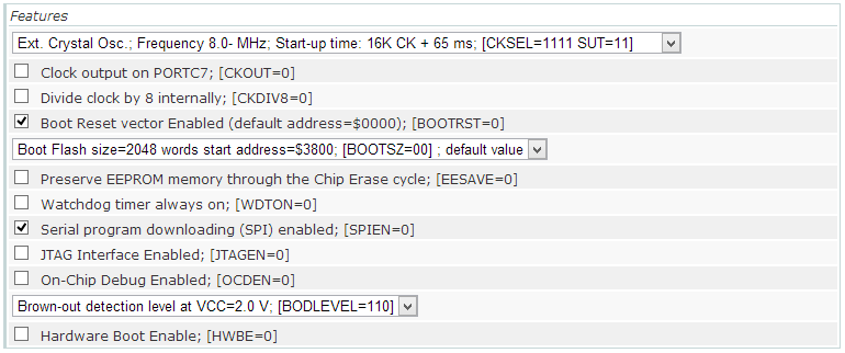
avrdude -v -v -patmega32u4 -cusbtiny -e -Ulock:w:0x3F:m -Uefuse:w:0xce:m -Uhfuse:w:0xd8:m -Ulfuse:w:0xff:m

avrdude -v -v -patmega32u4 -cusbtiny -Uflash:w:Caterina-lilypadusb.hex:i -Ulock:w:0x2F:m
You could disable the BOD fuse to save extra 0.02mA in sleep mode.
The bootloader also slightly differs from the “stock” Caterina bootloader because it passes control to the sketch immediately on board power-up and will only go in bootloader mode for 8 seconds on external reset (or if no sketch is present). This is done so that no time is lost between board power-up and the sketch powering down the unused peripherals. Source code of the bootloader here.
Funky v2 header pins
The side header of the Funky v2 started as intended Jeelabs’s JeePort, but that changed slightly as I advanced with the design. The reason for that is that JeePorts are Atmega328 specific and there is no information on which pins JCW will use in a future Atmega32u4 (if ever) based JeeNode. I still kept the overall idea of having a VCC-DIO-GND-3.3V-AIO-IRQ concept. Having said that, the Ports library will probably work with minor modifications.
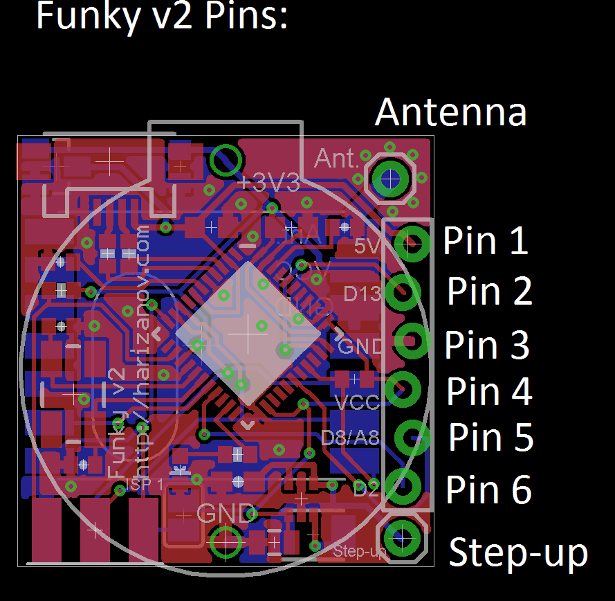
- Pin 1 connects to VUSB and provides +5V if the USB cable is plugged in. It can also be used to power the board from a 3.5-6V source, given the USB cable is disconnected. Typical application of this pin would be to provide 5V for sensors attached to the header
- Pin 2 connects to Digital 13, a special pin with timer output to drive IR LEDs for example.
- Pin 3 connects to GND
- Pin 4 connects to VCC (3.3V if powered via the USB or the voltage that your battery is providing if powered by a battery)
- Pin 5 can be used both as Digital 8 or Analog 8 in Arduino IDE, it is a pin that supports pin-change interrupts: Needed for RX of SoftwareSerial (TX can be digital any pin)
- Pin 6 is Connects to Digital 2 pin, also can be used for IRQs
The on-board LED is connected to Digital 1
Detecting USB connection
This is useful when determining weather we are running on battery power or USB power and take measures to reduce power consumption if we are running on battery. See my full post here.
void setup(){
  USBCON = USBCON | B00010000;
  pinMode(1,OUTPUT); // The on-board LED

  delay(550);  // Wait at least 550ms,may even require more on slow hosts (necessary)

  if (UDINT & B00000001){
  // USB Disconnected code here
  digitalWrite(1,HIGH);
  }
  else {
      // USB is connected code here
     digitalWrite(1,LOW);
  }
}

void loop(){
}
Power saving techniques
When running on battery, we aim to cut power consumption down as much as possible. The following code will bring Funky v2 to about 0.03mA sleep current when running with BOD fuse disabled and at 4Mhz. Also see a complete example on GitHub.
  ADCSRA =0;
  power_adc_disable();
  power_usart0_disable();
  //power_spi_disable();  //do that a bit later, after we power RFM12b down
  power_twi_disable();
  power_timer0_disable();   // Will also kill timekeeping, so be careful if your code relies on millis(); comment out if these are needed.
  power_timer1_disable();
  power_timer3_disable();
  PRR1 |= (uint8_t)(1 << 4);  //PRTIM4
  power_usart1_disable();

  // Switch to RC Clock
  UDINT  &= ~(1 << SUSPI); // UDINT.SUSPI = 0; Usb_ack_suspend
  USBCON |= ( 1 <<FRZCLK); // USBCON.FRZCLK = 1; Usb_freeze_clock
  PLLCSR &= ~(1 << PLLE); // PLLCSR.PLLE = 0; Disable_pll

  CLKSEL0 |= (1 << RCE); // CLKSEL0.RCE = 1; Enable_RC_clock()
  while ( (CLKSTA & (1 << RCON)) == 0){}	// while (CLKSTA.RCON != 1);  while (!RC_clock_ready())
  CLKSEL0 &= ~(1 << CLKS);  // CLKSEL0.CLKS = 0; Select_RC_clock()
  CLKSEL0 &= ~(1 << EXTE);  // CLKSEL0.EXTE = 0; Disable_external_clock

   // Datasheet says that to power off the USB interface we have to:
   //      Detach USB interface
   //      Disable USB interface
   //      Disable PLL
   //      Disable USB pad regulator

   // Disable the USB interface
   USBCON &= ~(1 << USBE);

   // Disable the VBUS transition enable bit
   USBCON &= ~(1 << VBUSTE);

   // Disable the VUSB pad
   USBCON &= ~(1 << OTGPADE);

   // Freeze the USB clock
   USBCON &= ~(1 << FRZCLK);

   // Disable USB pad regulator
   UHWCON &= ~(1 << UVREGE);

   // Clear the IVBUS Transition Interrupt flag
   USBINT &= ~(1 << VBUSTI);

   // Physically detact USB (by disconnecting internal pull-ups on D+ and D-)
   UDCON |= (1 << DETACH);

   power_usb_disable();  // Keep it here, after the USB power down
   rf12_initialize(storage.myNodeID,storage.freq,storage.network); // Initialize RFM12
   // Adjust low battery voltage to 2.2V
   rf12_control(0xC000);
   rf12_sleep(0);                          // Put the RFM12 to sleep

   power_spi_disable();
Licensed under a Creative Commons Attribution-NonCommercial-ShareAlike 3.0 Unported License.

Martin, this is pretty sweet! The only thing that concerns me is that you only provide 3 I/O pins with so much horsepower. How much do these boards end up costing you? It seems to me that it would be totally worthwhile to add another 8-pin strip on the other side. That would only add a couple of millimeters and allow you to add 6 more I/O (assuming VCC+GND pins). I.e. a perhaps 4mm extra space and you get 9 I/Os…
I intended this for interfacing with a single sensor, i.e. temperature, humidity, light level, PIR, pulse counter or sending IR/RF codes etc. It is just about the size of a button cell battery and can be powered by one, so having more pins would put more strain to the limited battery power anyway.
Anyway, I will probably create a bigger “cousin” to the Funky v2 with more pins available some day 🙂
What you’ve done here is really cool. I see that you have the RFM2Pi board. Do you know if anyone has interfaced with a Beaglebone Black? Is the RFM12 standard enough that a Funky v2 can talk to a JeeNode or other RFM12 implementation? Thx.
Bill
Hi,
I don’t think that it is ported yet, but that should be pretty easy to do, as it uses standard serial @ 3.3V. Yes, the Funky v2 talks happily to all RFM12b based nodes.
Pingback: Non-contact AC detection | Martin's corner on the web
Pingback: RFM12B End of Life | Martin's corner on the web