
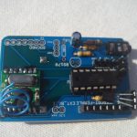
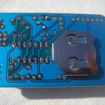
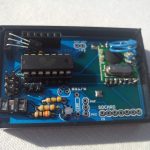
I have received 15 TinySensor v1.3 PCBs yesterday and am running tests. So far the ISP connector cannot be used because of a mistake I made on the PCB, but I assume this is fixable. I had to program the Attiny on a breadboard instead.
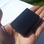
I have built a sensor to test out the RFM12b, DS18B20 and the analogue voltage divider port. Here are some pictures of it:
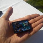
The next step that I plan is to try to interface the sensor directly to Raspberry PI’s UART and have one of the sensors acting as a gateway between the other sensors and the Pi.
Pingback: Fix for TinySensor v1.3′s ISP connector | Martin's corner on the web
Pingback: Running the Attiny84 @ 4Mhz with the internal oscillator | Martin's corner on the web
Pingback: RF12 Demo sketch for ATtiny84 | Martin's corner on the web
Very nice. Out of interest, who do you get to fab your PCBs ?
It is a local PCB fab house (doesn’t do international orders), quality is not the best, but they do small quantities. I hear seedstudio’s PCB service is good and cheaper, I may give it a try one day.
Pingback: Power saving techniques for the Attiny84 powered TinySensor | Martin's corner on the web
Pingback: TinySensor v1.4 plans | Martin's corner on the web