I have consolidated my accumulated so far experience on running the ATmega32U4+RFM12B based Funky v2 in low power mode in this example sketch. I managed to bring the power consumption down to 0.04mA, which makes it possible for the Funky v2 to run on CR2032 button cell battery. For the sketch to run optimally, I used different fuse settings from the default ones:
   External crystal 8Mhz, start-up 16K CK+65ms;
   Divide clock by 8 internally; [CKDIV8=0]  (We will start at 1Mhz since BOD level is 2.2V)
   Boot Reset vector Enabled (default address=$0000); [BOOTRST=0]
   Boot flsh size=2048K words
   Serial program downloading (SPI) enabled; [SPIEN=0]
   BOD=2.2V

   or:
   low_fuses=0x7f
   high_fuses=0xd8
   extended_fuses=0xcd
Basically I wanted to be able to run in the 2.2-3.3V range, so I had to bring down the BOD level a bit from the default 2.6V. In doing so, I had to take precautions not to overclock, so I set the fuses to run on 1Mhz. The sketch then speeds up to 4Mhz so it can talk over SPI to the RFM12B module. I also tried runnng with BOD fuse disabled and that saved me an extra 0.01mA, but it is a risky business to run without BOD at full speed.
The sketch does the following stuff:
- Checks weather it is running on battery or USB power and decides weather it needs to run in “power-save” mode
- If it runs on USB power, it will show a configuration menu over the serial port and allow customization of the band, NodeID, network group, sending frequency and weather ACKs are to be used. The settings will be saved in EEPROM. The menu will timeout after 30 seconds of inactivity and the sketch will start, however USB connectivity will not be disabled to allow re-programming.
- If it runs on battery, the sketch will power down almost all peripherals and only bring briefly up those that are necessary
- Based on the configuration, the node will sleep for a predefined period, then wake up and send battery readout + an incremented value. You can modify the sketch to send some useful payload, like sensor readout.
So overall this is quite good, but I still need to research on how to reduce the power consumption further.
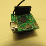
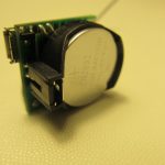
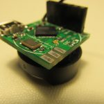
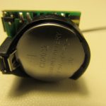
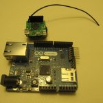
I have uploaded the test sketch and inserted a fresh CR2032 battery to see how many transmissions it can push thru..

Hi Martin.
Radio links rarely have “generic” solutions. Depending on the desired node topology, one can use different techniques to reduce the energy consumption to just about what’s necessary to get the job done.
One of the things I noticed when I started playing with the RFM12B module was that the receiver front end was mostly overloaded by the strong transmitter output (1~ 5dBm). This has a negative effect in the quality of the received signal and may end up in worse link conditions than what could be achieved with less power. In other words, the output power of the RFM12B does not have to always be at maximum but can be attenuated by as much as -17.5 dB, if link conditions allow it. Reducing transmitter power by 17.5 db would cause an immediate reduction to the energy needed for the signal to reach the receiver.
At the same time, reducing the Data Rate to about 9600bps or even less could increase effective range due to better BER; I get a 0% packet loss at 9600bps and about 3-10% at the default JeeLib rate of 49.261 bps, inside the house. Of course the transmission time is greater at a lower data rate but one has to consider all factors together, combining what works best.
Excellent comments, thanks!
I will have to experiment with tuned up settings and see how tings change.
Pingback: 73062 transmissions with the Funky v2 low-power code and CR2032 battery | Martin's corner on the web
Pingback: Reducing RFM12B transmission power | Martin's corner on the web