
[This project is obsoleted and not supported]
Three Channel WiFi Relay / Thermostat Board
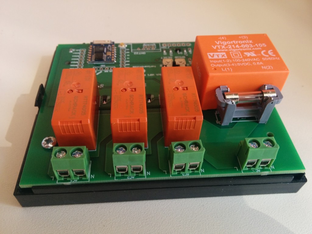
The Three Channel WiFi Relay / Thermostat Board is a open software/hardware multi-purpose relay board based on the ESP8266 WiFi SoC. It can control up to three AC or DC loads over the Internet using web UI or MQTT.
![]()
Highlights
- Powered by the popular ESP8266 WiFi SoC
- On-board power supply unit (optional)
- Up to three high quality 10A relays for switching AC or DC loads (see DC switching notes)
- Built-in web server with mobile device friendly UI and HTTP API to control the relays
-
- Thermostat function with weekly scheduling
- Manual relay control via the UI
- MQTT support
- NTP for network time and scheduling functionality
- Web server settings, including HTTP port and basic HTTP authentication setup
- Broadcast relay/sensor data using HTTP GET to services like ThingSpeak or emonCMS
- Integration with ThingSpeak for charting/analytics visualization
- Temperature sensor support (one of them, not both at the same time)
- DS18B20, supports multiple sensors
- DHT22 (AM2302)
NOTE: The board connects to and controls high voltage, knowledge and attention is required when installing it. It is recommended to use the compatible enclosure to prevent electrical shock.
Board schematic & layout
Three Channel WiFi Relay/Thermostat Board schematic and board layout files are available on GitHub
-
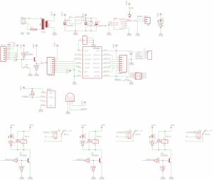
- Board Schematic
-
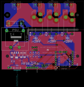
- Board Layout Design
The PCB is 2mm thick with 35 micron foil.
-
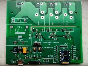
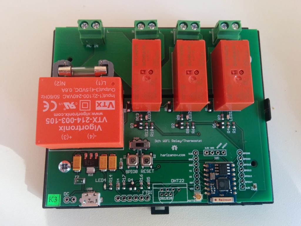
- Relay board less relays PSU, PSU fuse and screw terminals
-
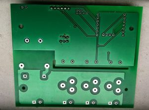
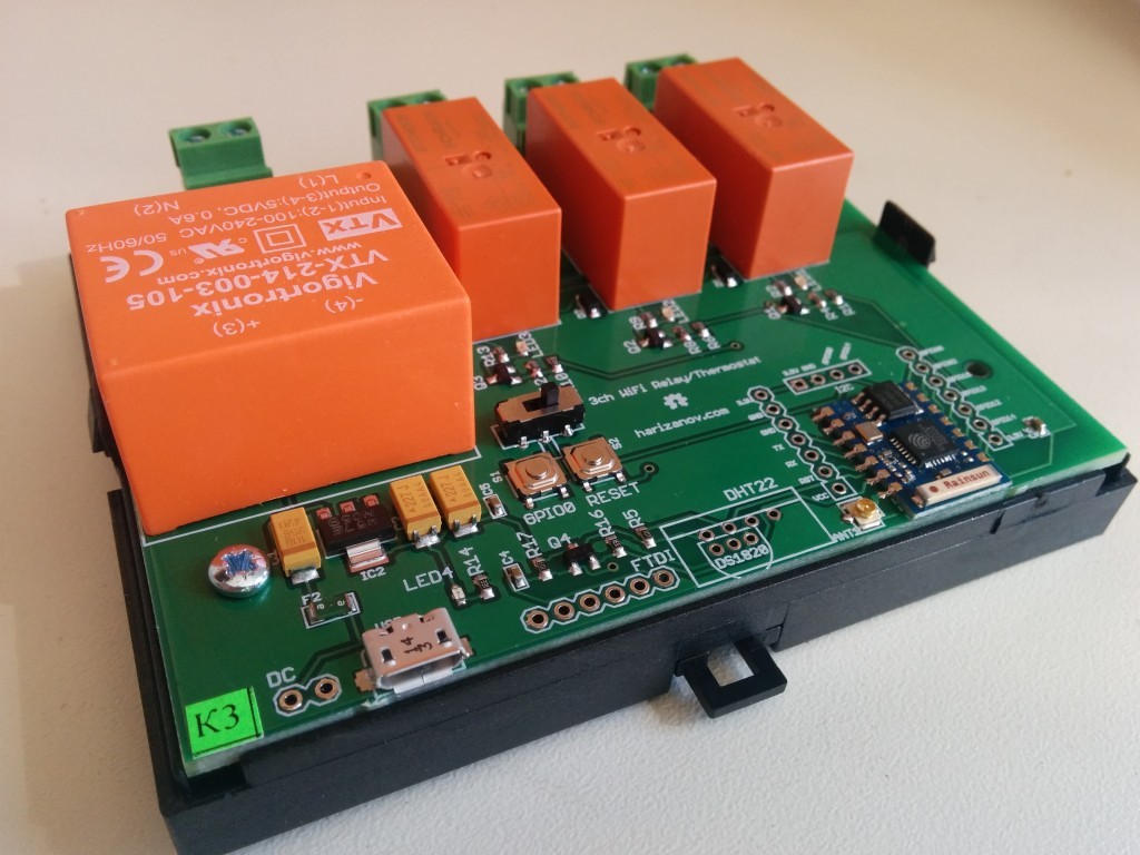
- Relay board less relays PSU, PSU fuse and screw terminals – bottom
Firmware
The latest firmware is available on Github. Firmware can be update using a *3.3V* FTDI cable, check the dedicated section of this WIKI.
Enclosure
The PCB is designed to fit in a high quality DIN rail-friendly enclosure. It is highly recommend to use the enclosure to protect yourself from electrical shock. Knock-out entries on the side lid allow custom configuration on the outputs:
-
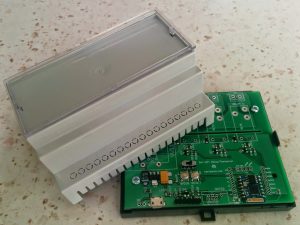
- The board in the box
-
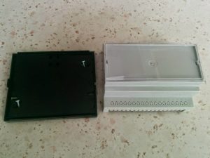
- Base and lid
-

- Transparent lid also available
-

- Two screws to secure the PCB
-

- DIN-rail mount
-
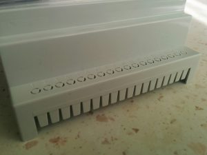
- Knock out entries
Powering it up
- The board can be powered as follows
- Through the on-board power supply module, if installed
- Via the USB plug
- Via the DC power terminal next to the USB plug (7-10V DC)
- Via the FTDI header using a 3.3V Logic Level FTDI cable (it still supplies 5V to the power pin)
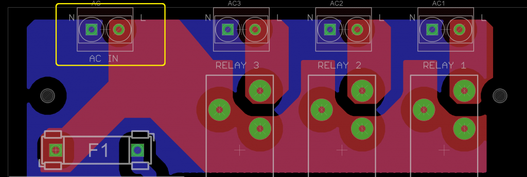
- Mind the live and neutral markings on the board, make sure Live wire connects to the L side of the screw terminal:

NOTE:
When connected to AC, handle the board with extreme care. Bottom and top of the high side of the board will be live and accidental touch may result in injury or death.
Connecting AC loads
Loads can be connected to the screw terminals next to the relays, please mind connecting Live and Neutral lines respectively.
NOTE: The relays are rated 10A, however I’d rather not utilize all three of them at maximum load, as that would cause 30A current to flow through the source AC screw terminal
Connecting DC loads
The board can be used for DC load switching, if the power supply unit is not populated on the board. Power the board from the USB connector or DC input.
Connect positive to the L and negative to the N side of the screw terminal.
Configuring the board
The board’s parameters are configured through web UI. Upon first boot, the board will enter Access Point mode and you will be able to see it as such by scanning the WiFi networks.
The Access Point name would start with “ESP_” followed by the access point MAC address. There will be no security or password. The access point will be switched off after a successful connection to the wireless network.
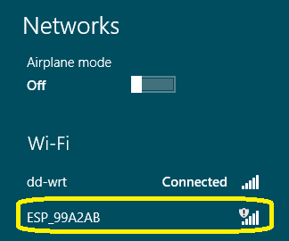
If the board does not show up, you may manually force the board into AP mode by pressing and holding the button labeled “GPIO0” for 3 seconds and then releasing it. NOTE: Mind the high voltage side of the board while doing so!!
Once connected to the access point, navigate your browser to http://192.168.4.1, if all worked well, this should take you to the main menu. Please note that some mobile phones will detect that the WiFi connection does not provide Internet and fall back to GSM data network. Make sure to disable mobile data so that your browser still uses that access point.
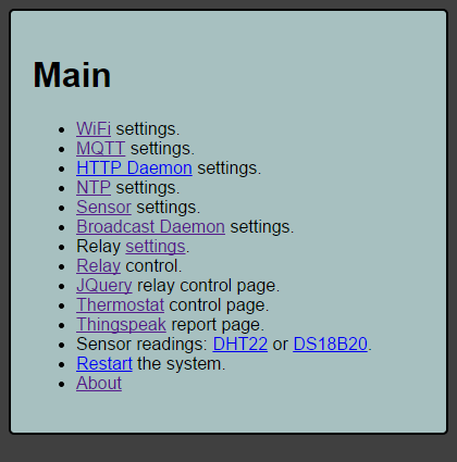
Main Menu
The main menu provides links to the respective sub-menus
WiFi connection setup
The WiFi connection menu lets you connect to your WiFi network. It will scan for the available networks and prompt you to chose it. Select the network, type in the network key and choose whether to use dynamic IP through DHCP or static IP address. Using static IP address makes most sense, as you would be able to access the board by its known IP address.

You will need to set up port forwarding if you wish to access the relay board from outside the network.
I use the following linux command to find the IP address of the ESP8266 modules connected to my network:
sudo arp-scan –retry 7 –quiet –localnet –interface=wlan0 | grep -s -i 18:fe:34
Sensor Settings
Sensor settings menu allows you to enable one of the two possible sensor daemons, DS18B20 or DHT22 (not both at the same time).
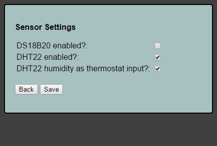
Multiple DS18B20 temperature sensors may be attached, thermostat function will use the one with smallest address.
The humidistat function can be enabled by choosing the humidity readout of DHT22 as input to the thermostat.
Temperature/humidity is checked every 30 seconds (hardcoded).
NOTE: Soldering the sensors directly on the board is not recommended as the PSU and the ESP8266 disperse heat and if the sensor is soldered on the PCB directly, there will be heat transfer and falsely high readings. For best results use wires and have the sensor outside the enclosure.
Relay Settings
This menu allows you to put a custom name to the relays e.g. “Boiler”, “TRV” etc
Second function is to implement relay “latching” i.e. preserve last relay state upon restarting/power loss recovery.
NOTE: Be careful with the function as it may energize the relay upon starting up the board if its last state was ON.
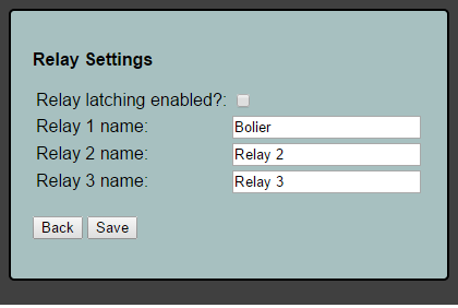
Relay 1 name is used as zone name in the thermostat control page.
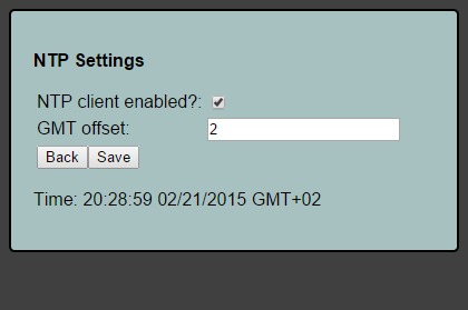
NTP settings
Network Time Protocol settings enable the NTP function; Must be enabled when using the thermostat scheduler function so that the relay knows the current date and time and act upon the schedule accordingly. NTP provides GMT time, add negative or positive offset accordingly.
Broadcast settings
This function allows the board to “broadcast” its basic state via HTTP GET.
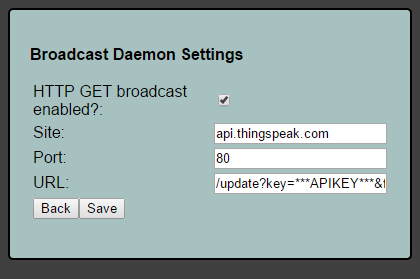
As example, the URL for thingspeak posting is formatted as follows:
/update?key=***APIKEY***&field1=%d&field2=%d&field3=%d&field4=%s&field5=%s&field6=%s
..and the board will sprintf relay 1 state, relay 2 state, relay 3 state, DS18B20 reading, DHT22 temperature reading, DHT22 humidity reading for the respective field.
Example broadcast URL string for emoncms:
/input/post.json?json={relay1:%d,relay2:%d,relay3:%d,ds18b20:%s,dht22t:%s,dht22h:%s}&node=21&apikey=***APIKEY***
NOTE: HTTPS / secure ports will not work
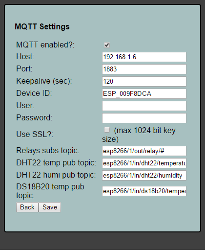
MQTT settings
MQTT settings allows enabling and configuring MQTT for the board. The board can subscribe itself to MQTT topic and control the relays from that topic. It will publish temperature and humidity (DHT22) data to respective topics as well.
NOTE: SSL does not currently work due to heap size issues when enabled.
Example of using mosquitto_pub to turn the relays on/off
mosquitto_pub -d -t esp_009F8B46/out/relay/1 -m 1
mosquitto_pub -d -t esp_009F8B46/out/relay/1 -m 0
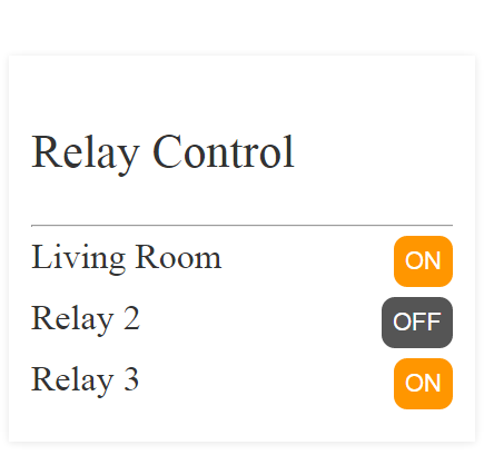
Relay control UI
The relays can be controlled via a simple mobile device friendly UI. Just click on the On/Off button to change their state. Relay names are set via the Relay Settings menu.
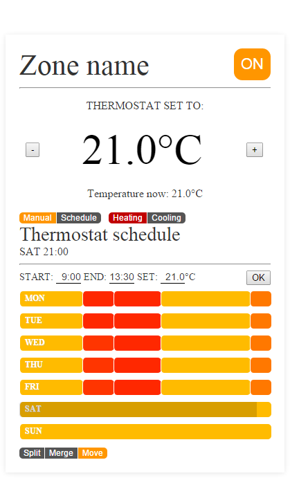
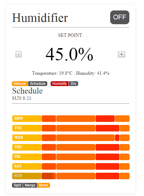
Thermostat/Humidistat function
Thermostat function allows setting manual setpoint or using weekly schedule. NTP time must be enabled when using schedule. Thermostat code only controls relay №1.
The schedule is adjusted by moving the slides to the left or right, these represent schedule blocks on a 24 hour scale. Block boundaries can be moved, blocks can be merged or split into more detailed schedule blocks. Each block has setpoint, color represents the setpoint value (yellow-orangish-red).
Thermostat will not function until it is in “ON” state. Manually setting the setpoint will switch to “Manual” mode. Switching off the thermostat function will force off relay 1.
Cooling mode will invert relay logic, I plan to use that for controlling fan coils in cooling mode during the summer.
Setpoint changes color to RED when relay 1 is activated and black when relay 1 is off.
Humidifier function, enabled via the ‘Sensor settings’ menu:
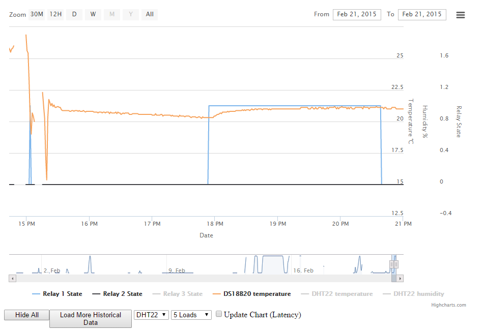
Thingspeak report integration
If broadcasting to thingspeak, a report that is using JavaScript to fetch data from thingspeak and render it is available
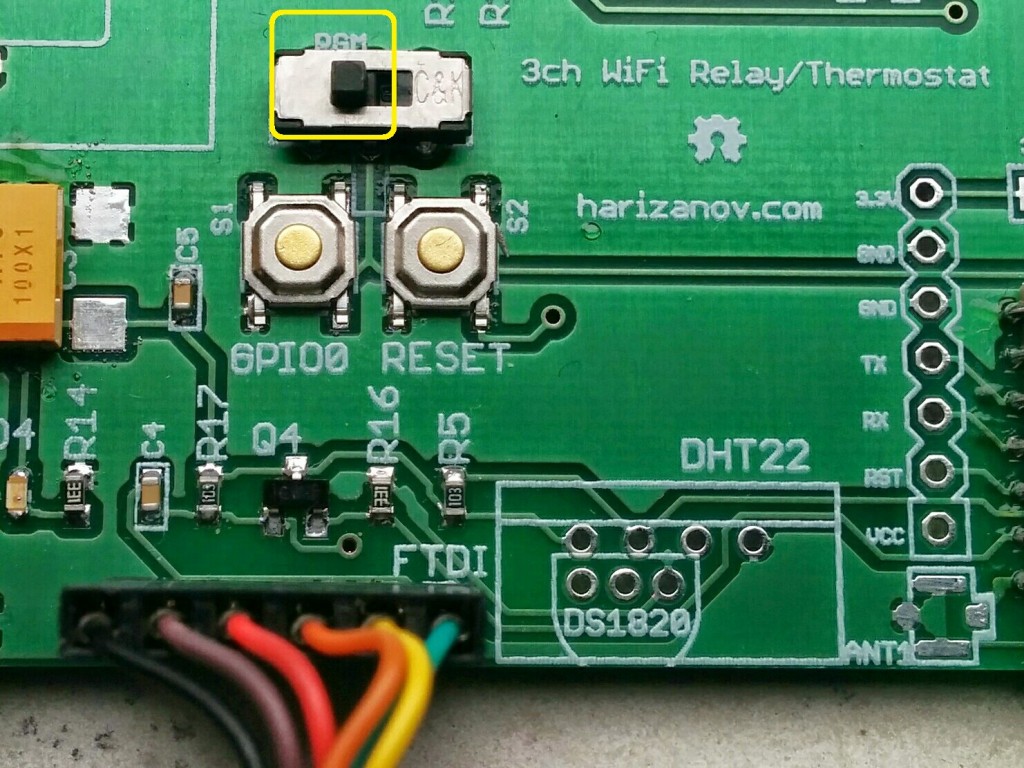
Firmware update
To change firmware, set the programming switch to “PGM” position and attach *3.3V* FTDI cable with GND (black wire) towards the USB plug:
Firmware update tools
Python under Linux
Use the default baud 115200;
sudo ./esptool.py --port /dev/ttyUSB0 write_flash 0x00000 firmware/0x00000.bin
sudo ./esptool.py --port /dev/ttyUSB0 write_flash 0x40000 firmware/0x40000.bin
sudo ./esptool.py --port /dev/ttyUSB0 write_flash 0x12000 webpages.espfs
sudo ./esptool.py --port /dev/ttyUSB0 write_flash 0x3C000 blank.bin
Also see the ESP8266 WiKi for more details on uploading code.
Do not forget to flip back the PGM switch to the right side when done, or the code won’t start and the module will be stuck on bootloader mode.
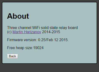
About
Provides firmware version and free heap size information
HTTP API
Relays can be controlled via the UI or using HTTP GET requests
Example:
http://RELAYADDRESS/control/relay.cgi?relay1=1&relay2=0&relay3=1
The above HTTP request will switch relays 1 and 3 ON and set relay 2 to OFF. If security was enabled, you will need to provide means for HTTP Basic authentication.
The current relay states can be retrieved using the following request
http://RELAYADDRESS/control/relay.cgi?state
This returns a JSON string with the current relay states and their names (set via the UI):
{"relay1": 0
,"relay1name":"Boiler",
"relay2": 0
,"relay2name":"Relay 2",
"relay3": 0
,"relay3name":"Relay 3" }
The following API provides temperature sensor readout on top of the relay state:
http://RELAYADDRESS/control/state.cgi
Returns:
{
"relay1": "0",
"relay2": "0",
"relay3": "0",
"DHT22temperature": "N/A",
"DHT22humidity": "N/A",
"DS18B20temperature": "58.87"
}
Using the HTTP API example in Python
#!/usr/bin/python#!/usr/bin/python
import urllib2, base64, json, time
from urllib2 import Request, urlopen, URLError, HTTPError

username="admin"
password="pass2"
DEVICE1="192.168.1.25"

def getData (request):
        base64string = base64.encodestring('%s:%s' % (username, password)).replace('\n', '')
        request.add_header("Authorization", "Basic %s" % base64string)
        try:
            result = urllib2.urlopen(request)
        except HTTPError as e:
            print 'The server couldn\'t fulfill the request.'
            print 'Error code: ', e.code
            return -1
        except URLError as e:
            print 'We failed to reach a server.'
            print 'Reason: ', e.reason
            return -1
        else:
            return result.read().strip()


def getRelayState(device, relaynum):
        request = urllib2.Request("http://"+device+"/control/state.cgi")
        result = getData(request)
        data = json.loads(result)
        return data["relay"+str(relaynum)]

def setRelayState(device, relaynum, state):
        request = urllib2.Request("http://"+device+"/control/relay.cgi?relay"+str(relaynum)+"="+str(state))
        result = getData(request)
        return result

def getDS18B20Reading(device):
        request = urllib2.Request("http://"+device+"/control/state.cgi")
        result = getData(request)
        data = json.loads(result)
        return data["DS18B20temperature"]

print "Relay 1 state is: " + getRelayState(DEVICE1,1)
print "DS18B20 temperature sensor reading is: " + getDS18B20Reading(DEVICE1)
print "Turning relay 1 on"
setRelayState(DEVICE1,1,1)
time.sleep(5)
print "Turning relay 1 off"
setRelayState(DEVICE1,1,0)
Buy one
The project is available to purchase from my shop.
Credits
I have used the code from the following sources for this project
- The ESP-HTTPD project by Jeroen, beerware license
- The ESP-MQTT project by Tuan PM, MIT license
- JSON jsmn library, Z Serge, MIT license
- Open heating controller/thermostat scheduler by Trystan Lea
- ..ping me if I missed something/someone
License
This project is licensed under Creative Commons Attribution-NonCommercial-ShareAlike 3.0 Unported License.

Please get in contact with me, if you would like to use the code for a commercial project.
Donations
If this code helps you in your non-commercial project and you would like to buy me a beer or dinner, it will be greatly appreciated 🙂
Pingback: WiFi Thermostat with weekly scheduler | Martin's corner on the web
Pingback: DIY Internet connected smart humidifier | Martin's corner on the web
Pingback: A couple of good (ESP8266) examples… | esp8266hints
Pingback: Ensuring comfort climate with smart humidifier - Embedded projects from around the web
Pingback: Firmware Over The Air (FOTA) for ESP8266 SoC | Martin's corner on the web