
[This project is obsoleted and not supported]
Funky v3
This is v3 of my “Funky” Arduino clone, specifically designed to be small, with on-board radio module and for low power applications.
Highlights
- Board size is 20×21.2mm (0.78″x0.83″)
- Weighs 3 grams (0.11 oz)
- Compatible with Arduino IDE
- ATMega32U4 MCU, the same as processor used in the popular Arduino Leonardo
- No need for external programmer to upload new sketch – just use micro USB cable
- Equipped with 433/868 wireless RFM12B or RFM69CW transceiver module
- Runs on 8 Mhz and can be powered from 2.7-3.3V power source, including coin cell battery
- Low power operating mode
Board schematic & layout
Funky v3 schematic and board layout files are available on GitHub
-
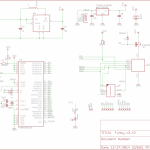
- Funky v3 schematic
-
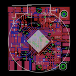
- Funky v3 board layout
Pins legend
- Pins mapping:
-
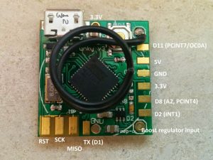
- Top view
-
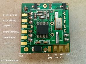
- Bottom View
-
Powering it up
- Via the USB
- Simply plug in the Funky to micro USB cable and it will be powered up.
- NOTE: Please remove any battery attached when plugging into USB.
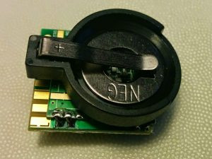
- Coin cell (CR2032)
- Coin cell holder can be directly soldered on the bottom of Funky v3
-
-
- Optional coin cell holder CR2032, not included
-
- If you wish to use CR2032 battery in combination with the optional LTC3525 boost regulator, you will need to bend the positive pin and route that with a wire to the boost regulator entry.
- AA(A) Batteries
- Use two AA(A) batteries on the VCC and GND to supply 3V to the Funky v3
- Use 3 AA(A) batteries connected to the 5V and GND to supply 4.5V to the on-board LDO that will regulate it to 3.3V
- Boost Regulator
- The board carries an option for the LTC3525ESC6 (3.3V version) boost regulator and supporting elements to be included, this is useful when you wish to power the board from a 0.8 – 5.5V source and get that regulated to 3.3V.
-
-
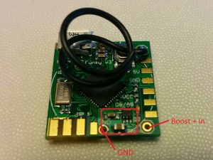
- The LTC3525 and supporting passive components. Note the boost regulator entry
-
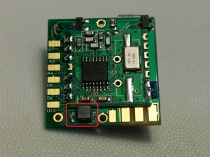
- The boost regulator inductor
-
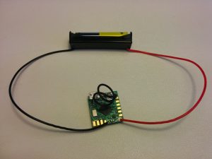
- Powering the Funky v3 from single AAA battery
-
- Side Headers
- Funky v3 can be powered from the side headers (3.3V and 5V possible)
- If your project requires it, you may solder 6×2 headers to the side pins and another 4×2 on the bottom pins as shown below
-
-
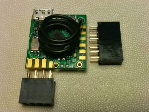
- Optional side headers (not included)
-
- The header pins will require slight filing to shorten the metal pins length for best fit
Arduino IDE
- Setting up
- Download and install the latest Arduino IDE from the official Arduino site. Setting it up is straight forward.
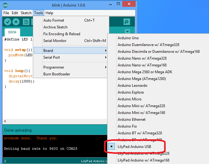
- Chose the board type
-
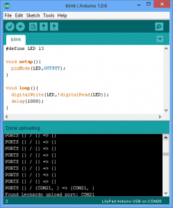
- Select “LilyPad Arduino USB” as board type, it uses the same MCU/Clock speed as the Funky v3, so I have decided to use that as board type rather than own custom board type that would require more difficult user setup:
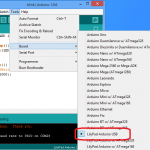
Click to enlarge
-
- Libraries
Using the RFM69CW radio module instead of the RFM12B is possible, just make sure you include the following define:
#define RF69_COMPAT 1 // define this to use the RF69 driver i.s.o. RF12
The RFM69CW module must be initialized as soon as possible in the sketch as until initialized, it is quite power-hungry and will brown-out the Funky v3 after a short while. A 10uF 0805 SMD ceramic capacitor must be soldered on the boost regulator circuitry to support the RFM69CW module. It also uses double the transmission power to that of a RFM12B (45mA compared to 23mA), so may be less suitable for low-power operation mode.
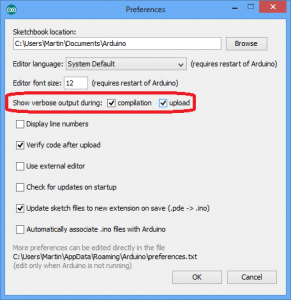
- Uploading new sketch
- Just hit the ‘Upload’ button in Arduino IDE.
- If for some reason the sketch won’t upload, hit the ‘Reset’ button on the Funky v3 just when the IDE starts looking for the board, this is easily identifiable by the text “PORTS {} / {} => {}” in the debug window as pictured below:
-
-
- The module comes with bootloader and the RF12Demo sketch installed, so you may start toying immediately.
- Blinky example
- Grab the Blink example from GitHub and upload to the board. The on-board LED should blink every second
- LED is connected to pin digital 13
Using the RFM12B/RFM69CW
- Prerequisite: the Jeelib Arduino library, see the above “Library” section
- Powering up the module
- The RFM12B module must be explicitly powered up by writing LOW to Digital 4. Make sure to power up the module *before* any attempt to initialize it, otherwise it will simply fail.
-
 pinMode(4,OUTPUT); // Funky v3 RFM12B power control pin
 digitalWrite(4,LOW); //Make sure the RFM12B is on, yes LOW is ON
 delay(100); // Delay (or sleep) to allow the RFM12B to start up
- Initializing the radio module
- The following code will initialize the RFM module to NodeID=22, 868Mhz and network group of 210
-
rf12_initialize(22,RF12_868MHZ,210);
rf12_control(0xC000); // Adjust low battery voltage to 2.2V, only for RFM12B
rf12_sleep(0);  // Put the RF module to sleep
- Send example
- The following code will send a payload structure over the radio link
-
typedef struct {
	  int temp;	// some structure as payload
} Payload;
Payload temptx;

rf12_sleep(-1);  // Wake up RF module
while (!rf12_canSend())
            rf12_recvDone();
rf12_sendStart(0, &temptx, sizeof temptx);
rf12_sendWait(2);  // Wait for RF to finish sending while in standby mode
Low power
Running on batteries requires special care to cut power consumption to its lowes possible. This is possible by both hardware architecture and software code.
- Detecting USB
- It makes sense to keep USB connectivity ON when we are powered by the USB and not running on battery power. That enables us to use serial debugging/configuration of the module. To identify if we are running on battery or plugged into USB, use the following code:
-
 USBCON = USBCON | B00010000;

 delay(550); // Necessary, some systems may even require longer delay

 if (UDINT & B00000001){
 // USB Disconnected; We are running on battery so we must save power
 }
 else {
// Running on USB power, we can be wasteful
 }
- The following code will reduce power usage to maximum possible extend by switching off certain peripherals and switching to the internal RC rather than the external crystal. This will allow the Funky v3 to run longer on battery.The code will disable USB connectivity, so you will need to hit the ‘Reset’ button to upload a new sketch:
-
 ADCSRA =0;
 power_adc_disable();
 ACSR |= (1 << ACD); // disable Analog comparator, saves 4 uA
 power_usart0_disable();
 //power_spi_disable(); /do that a bit later, after we power RFM12b down
 power_twi_disable();
 power_timer0_disable(); // Do not disable if you need millis()!!!
 power_timer1_disable();
 power_timer3_disable();
 PRR1 |= (uint8_t)(1 << 4); //PRTIM4
 power_usart1_disable();
 // Switch to RC Clock
 UDINT &= ~(1 << SUSPI); // UDINT.SUSPI = 0; Usb_ack_suspend
 USBCON |= ( 1 <<FRZCLK); // USBCON.FRZCLK = 1; Usb_freeze_clock
 PLLCSR &= ~(1 << PLLE); // PLLCSR.PLLE = 0; Disable_pll
 CLKSEL0 |= (1 << RCE); // CLKSEL0.RCE = 1; Enable_RC_clock()
 while ( (CLKSTA & (1 << RCON)) == 0){} // while (CLKSTA.RCON != 1); while (!RC_clock_ready())
 CLKSEL0 &= ~(1 << CLKS); // CLKSEL0.CLKS = 0; Select_RC_clock()
 CLKSEL0 &= ~(1 << EXTE); // CLKSEL0.EXTE = 0; Disable_external_clock

 // Datasheet says that to power off the USB interface we have to:
 // Detach USB interface
 // Disable USB interface
 // Disable PLL
 // Disable USB pad regulator

 // Disable the USB interface
 USBCON &= ~(1 << USBE);

 // Disable the VBUS transition enable bit
 USBCON &= ~(1 << VBUSTE);

 // Disable the VUSB pad
 USBCON &= ~(1 << OTGPADE);

 // Freeze the USB clock
 USBCON &= ~(1 << FRZCLK);

 // Disable USB pad regulator
 UHWCON &= ~(1 << UVREGE);

 // Clear the IVBUS Transition Interrupt flag
 USBINT &= ~(1 << VBUSTI);

 // Physically detact USB (by disconnecting internal pull-ups on D+ and D-)
 UDCON |= (1 << DETACH);

 power_usb_disable(); // Keep it here, after the USB power down

 // Initialize and put the RFM12B to sleep, make sure it is powered before attempting to talk to it..
 rf12_initialize(storage.myNodeID,storage.freq,storage.network,1600); // Initialize RFM12
 // Adjust low battery voltage to 2.2V
 rf12_control(0xC000);
 rf12_sleep(0);                          // Put the RFM12 to sleep
 power_spi_disable();
-
- Sleeping
- You can put the MCU to sleep to save power
-
for(int j = 0; j < 1; j++) {    // Sleep for j minutes
   Sleepy::loseSomeTime(60000); //JeeLabs power save function: enter low power mode for x seconds (valid range 16-65000 ms)
}
- Pin Change Interrupts
The RFM12B_test example sketch will
- Detect if connected to USB
- If connected to USB, it will run a configuration menu on serial for 20 seconds
- If will send a payload structure of a incrementing value and VCC readout every 20 seconds
This project is licensed under a Creative Commons Attribution-NonCommercial-ShareAlike 3.0 Unported License. 
Pingback: Using DS18B20/DHT22 temperature sensor with internal pull-up resistors rather than external ones | Martin's corner on the web
Pingback: Spectrum analysis with RFM12B | Martin's corner on the web
Hi Martin,
quick question, can I power Funky V3 from 9V battery via 5V pin?
MCP1703 operates in range of 2.7 up to 16V however
I would say no because VBUS is connected to ATMEGA32U4 via pin 2-UVCC and pin 7-VBUS.
Moreover I found a bug in https://harizanov.com/wiki/wiki-home/funky-v3/funky_v3_r3-sch/#main,
Label VCC 3.3V !!! is incorrect it should be 5V or VBUS as per your PCB layout.
Regards
Vitek
Sorry I meant this picture https://harizanov.com/wiki/wiki-home/funky-v3/funky-bottom/#main
“I would say no because VBUS is connected to ATMEGA32U4 via pin 2-UVCC and pin 7-VBUS.”
Exactly.. this is a bit unfortunate, maybe I should have placed a diode just before the voltage regulator. Too late now .
Thanks for pointing out the error on the ISP pins labeling, I just don’t have the original image to edit it; No harm will be done anyway; I’ll have to spare some time and revise it appropriately.
Hi Martin,
in some of your blogs I found the hint to look into your webshop — and especially for this nice little device here I would be interested to buy one. Is this possible? Your homepage does not show any “shop” link — at least I cannot find one … I think once it was there?!
Thanks a lot in advance!
arwed
Hello,
yes, there used to be a shop where I’d sell the exta units I had..I don’t have free time to support it any more, plus am out of stock on products.
Cheers,
Martin
Martin,
is there anything available on the market that comes close to the Funky? It is exactly what I’m looking for, but I don’t have the means to fabricate the board myself…
Regards,
Mike
Hi,
Have you tried the Moteino? The form factor isn’t same, but function-wise should be just fine.
I do have few left, just less the radio modules. How many units do you need?
Cheers
Hey Martin,
Thanks for great early work on the Funky boards. I have two questions I hope you can answer from your experience:
1.) Since you have both the boost regulator (which works on battery power) and the linear voltage regulator (which works on USB, based on schematic), how is the performance in general? What I’m specifically interested in knowing is – on battery power, is the MCP1703 happy with having 3.3V on its VO pin (from the boost) and nothing on it’s input? Or do we see some reverse current flow back through it and turn it on? Same thing for the boost – when powered by USB, is the boost regulator still switched off with 3.3V on its output (from the linear reg) or is it reverse powered?
2.) What’s the function of the MOSFET on pin D4? It looks like it turns the radio on/off when needed, but not sure why D4 is also connected to RESET.
Thanks!
Hi,
Regarding 1) True, I have a series of posts on this issue, see http://harizanov.com/2013/03/high-sleep-current-issue-with-funky-v2-sorted-out/ and http://harizanov.com/2013/08/every-%CE%BCa-counts/ for example. Bottomline is that I ended up using the Torex XC6206 which works well.
2) With the default state of RFM12B OFF the pins on an unpowered module look like a series resistance + ESD diode drop to ground . This loads down the SPI bus lines, giving the FLASH programmer a difficult time enforcing a clean waveform. Therefore D4 ensures the module is force powered during reflash with ISP programmer