
The ESP8266 DHT22/LED blinker project grew into an M2M relay board project with the following features in mind:
- Relatively small (10x5cm) PCB
- Powered via the onboard power supply or externally via a micro-USB plug
- Has three 2A Sharp Solid State Relays (later version has 8A SSR)
- DHT22 humidity/temperature and/or DS18b20 temperature sensor support to use for thermostat purposes
- WiFi (of course) in Static/Dynamic IP mode
- Native MQTT support (both publish and subscribe, controlling the relays and reading sensors over MQTT)
- HTTP/JSON API for setting/getting relay board properties
- Fancy jQuery UI for remote control via smartphone/tablet/laptop from anywhere in the world
- Web-configurable WiFi/MQTT/Sensor settings
- NTP support
- In the pipeline
- Basic HTTP authentication to protect the web interface
- Dynamic DNS support so that the module’s IP is always known
- I2C status display support
- Custom made plastic box/cover
- Scheduling functionality
I’ve created a prototype PCB to test the concept, used a quick turnaround PCB service that was neither quick nor of good quality. The initial idea was something like this:
-
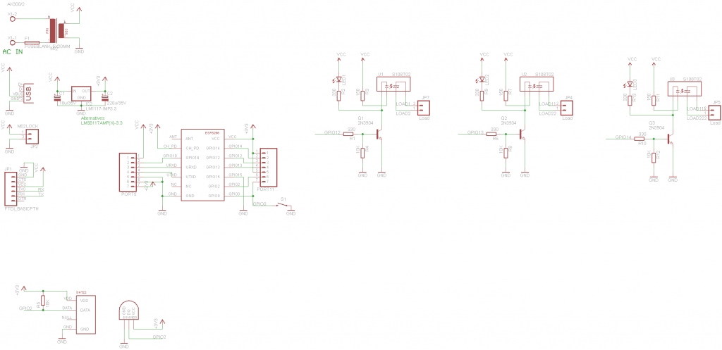
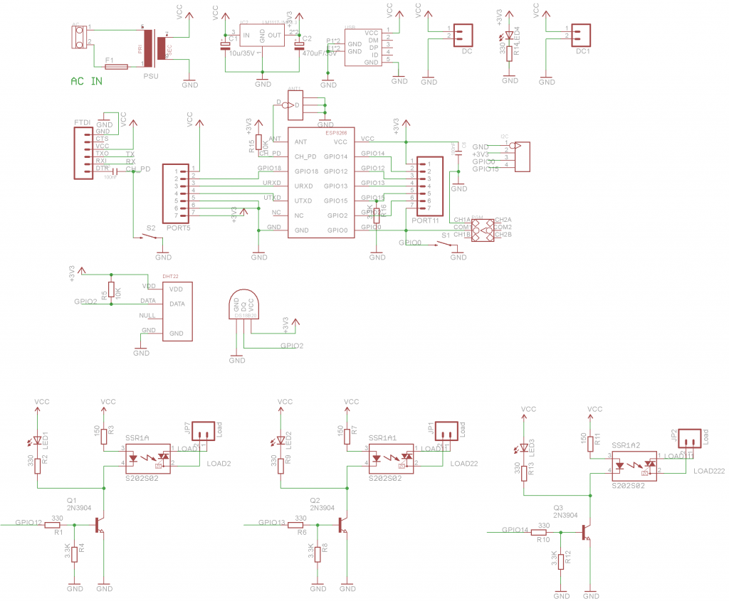
- v1 Schematic
-
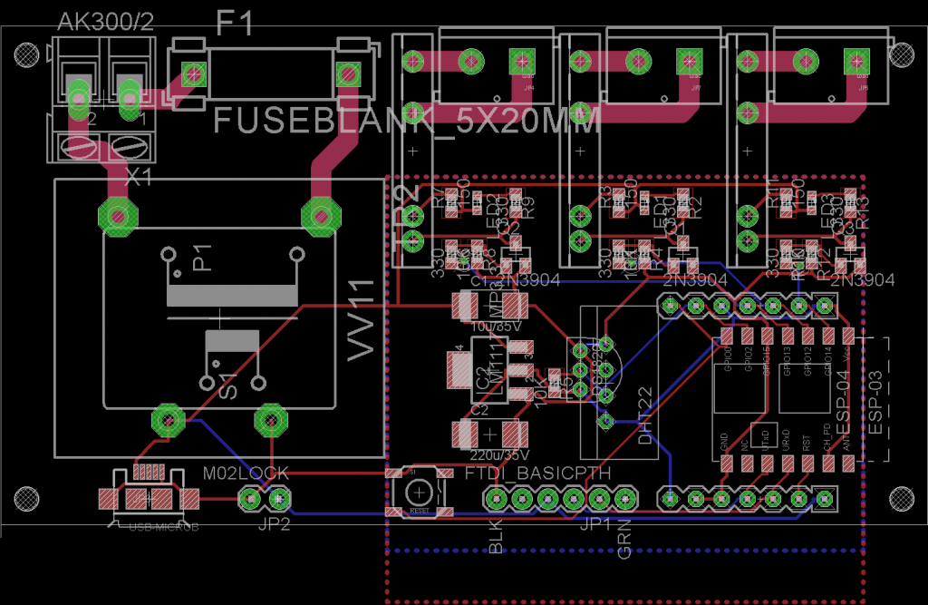
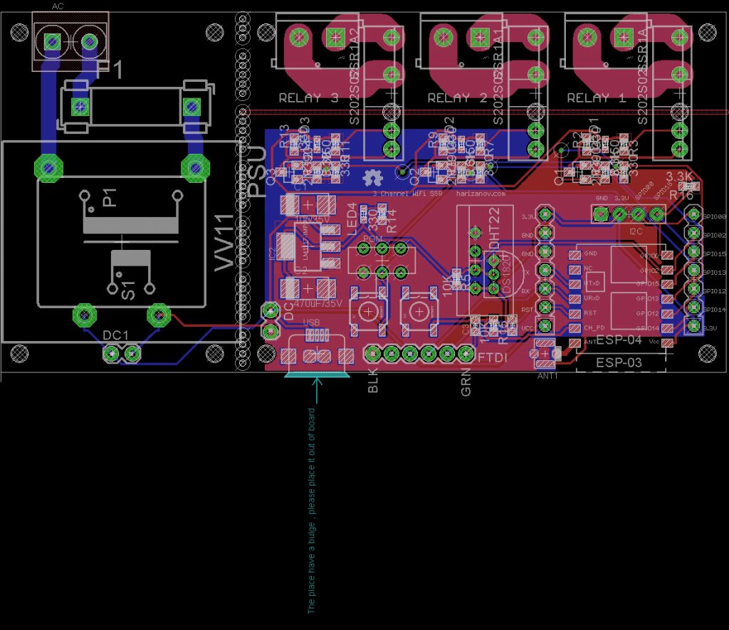
- v1 Board Layout
-
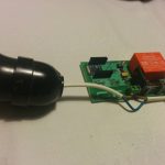
- v1 Board With one SSR populated and a light bulb attached to test

The v1 board had some design flaws, but overall works well. Here is a video, the software was at early stage then:
I’ve since then added native MQTT support based on Martin Hubáček’s mbed MQTT for LwIP. That implementation is quite basic and lacks some features so I plan to replace it with Tuan PM’s fresh MQTT for ESP8266 code in the future. The board currently publishes the readings of the DS18B20 temperature sensor to “ESP8266/in/ds18b20/temperature” topic and subscribes itself to “ESP8266/out/gpio/#” to watch for on and off commands for the three SSRs on GPIOs 12-14. The publish and subscribe topics are hardcoded now, but I am working on a configuration web interface where all these settings would be exposed.
MQTT makes it quite easy to implement external business logic, I use Node-Red for the purpose and have implemented complex rules that trigger my boiler heater element and a heat exchanger contour TRV.
-
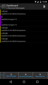
- Visualising MQTT with Android’s MyMQTT
-
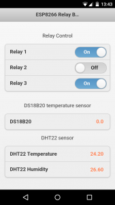
- The jQuery control web UI
-
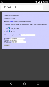
- The Wi-Fi configuration page; Fixed or dynamic IP address can be assigned
-
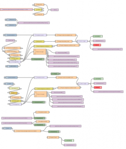
- Node-Red business logic that drives the relay board
I also added a jQuery powered control UI with background refresh using the board’s HTTP/JSON API; it updates automatically if the state changes from another session or MQTT control packet.
The configuration UI is intentionally in the old-style plain HTML so that it can be rendered even when the board is in AP configuration mode and the connected device can’t pull the jQuery libraries online.
NTP support is also there and I plan to use that for some basic scheduling functionality; Given the HTTP API and MQTT support, that seems less and less practical, but I still do plan to add it at some point in time.
Alternatively, one could use the nodeMCU ESP8266 Lua firmware instead and make all sorts of fancy use of the relay board with custom scripting some thermostat functions for example.
I’ve used the v1 board to control a contactor that switches on and off the heater element in my boiler and controls a Non-Mechanical Thermo Electric Actuator that opens heat exchanger contour in case my fireplace with water jacket produces hot water that exceeds the boiler’s current temperature and thus aids or completely replaces the electric heater element.
-
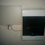
- Enclosed in a plastic box next to the boiler’s breaker box
-
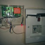
- Covers removed; Box has a status led and a on/off switch to kill the power. The Contactor in the breaker box has a manual switch as per wifey’s request
-
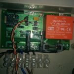
- The SSR board, DS18b20 temperature sensor wired to a probe hole in the boiler.
-
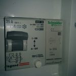
- Fuse and the Contactor that is controlled by the relay board
-

- CALEFFI non mechanical TRV
-

- TRV, this opens/closes heat exchanger contour
The HTTP API exposes the status of the relays and sensors as JSON string
http://IP/ds18b20.cgi returns { “temperature”: ” 55.0″}
http://IP/dht22.cgi returns { “temperature”: ” 24.4″, “humidity”: “44.5” }
http://IP/gpio.cgi returns the state of the relays { “gpio12”: “0”,”gpio13″: “0”,”gpio14″: “0”}
Relays are switched on/off using a HTTP GET with query string: http://IP/gpio.cgi?gpio12=1&gpio13=0&gpio14=0
Since the module can provide JSON status string, we can use freeboard.io to query and visualise the data directly with no proxying, I have only set a router rule to port forward the HTTP traffic of an externally visible port to HTTP port 80 of the ESP8266 relay board:
-
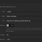
- Freeboard.IO Data Source set up
-
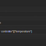
- Boiler Temperature filter
-
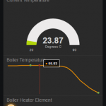
- Dashboard to show boiler’s temperature over time and the heater element state
So freeboard.io now talks to the relay board to provide some insights on is state, a 3 minute effort to illustrate the power of the Internet of Things.
I’ve decided to swap the 2A relays I used in v1 of the board with 8A ones and also made some fixes to the board design, here are the plans for v2:
-
- v2 Schematic
-
- v2 Board Layout
I will be ordering few test boards of the v2 and blogging my progress once they are with me.
Switching larger loads is quite easy by adding a AC-AC SSR on top, I suggest Fotek’s line like this one. Some models with heat sink can switch up to 80A, more than I’ll ever need. Connecting the on-board SSRs in parallel to increase the load current is *NOT* an option, just a note to those curious to try (myself included).
Once I get all this working the way I imagine it, I will make the board design files and source code available on Github, and will offer a limited number of pre-built boards in my shop. You want one, trust me.. 😉
Follow me on Twitter to get the news first when these are available.
Follow @mharizanov
Great work! Almost exactly what I need. So if I understand correctly DS18B20 is 1-wire and therefore it’s possible to connect multiple such sensors to the board (as I have a need for 2 or 3)? Can’t wait for this to hit your shop 🙂
Yes, but the current code only supports one sensor. That will change in the future as I too can see the benefit of having multiple sensor reading to make decisions about switching on/off the relays.
Sorry, but I cannot find any link to the source code, neither this last version nor the previous one. Is it available for testing?
Not yet, I will make it available in a while, all is hard-coded to my needs now. Working on making it all configurable via the web UI.
I’m interested in the NTP support — I’m looking to build a device that needs reasonably accurate frequency (i.e. long term time stability). What approach did you take for the NTP support?
I used the sntp code found here: https://github.com/TomerCo/ESP8266-AT/tree/master/at_v0.20_on_SDKv0.9.3/user
Works as a treat
Great work – I am looking to do the same!. I’m currently using a Tado system linked with Node-Red.
I have an ESP8266 with oled and mqtt just showing the values for Temp/power/hot water.
A couple of questions: do you need 5v on the board? Could the ssr be triggered by 3.3v instead. You could then simplify the board by removing usb and the psu components. (There is a VIGORTRONIX VTX-214-003-103 3v converter). Note: I am not an electronics person!!
Good work with the OLED MQTT display, I saw your project on Twitter.
I use Ben’s Node-RED geofencing node with Owntracks to achieve same result as Tado, check http://www.hardill.me.uk/wordpress/2014/11/30/node-red-geofence-node/ ; http://owntracks.org/
The SSR can be triggered by as low as 1.7v @ 25ma, you still need transistor to drive it as the GPIOs can only source 10mA
I prefer the 5V power supply so that the board could be powered by USB as alternative to the PSU. Look at v2 board revision, the PSU part can be broken off and the board can be USB powered
Ah, ok. That makes sense. I look forward to seeing the v2 board – I will be making one 🙂
Hi Martin! 🙂
Extraordinary work You do with these little buggers 🙂
I have been following your previous blinking led project and now found this. Parts of it seems to do exactly what I want, so I wonder if I could use your code and strip it of the things I don’t need. What I want is to use a few esp8266’s standalone with just a ds18b20 on them. I’m after building a few identical battery-powered temp-measuring nodes that will sit in different rooms in the house, each publishing one measurement to a mqtt-server every ten minutes and then go into deep sleep. They really don’t need to awaken more often than every 10 minutes. They awaken, do one conversion, send that to the server and immediately go to sleep again. I have constructed my own shunt-control system and want to have measurements from more than one location in the house. I can then make my own logic in the shunt-control system, for example filter out measurements that deviate more than a certain value from the average of all the other readings, then take the average temperature of the remaining ones as a basis for the shunt event.
Hi it looks really cool! I have one question regarding the DS18B20 , do You remember the sensor ID, or for this it will be neceassery to connect some EEPROM module ?
Hi,
It just scans the 1-wire bus and reads the first sensor it finds, no need to know the sensor ID upfront. The code supports only one sensor now, but I plan to change that; the config UI will allow to give those ‘human readable’ name.
Martin – how are tests going? Is everything stable – what software did you use to make board (I think it’s bigger than free Eagle allows) – would be nice to do some tests on my own 🙂
Hi,
slower than I originally thought – both on the hardware and software side. Lots of challenges to tackle, but I’m moving forward. I have a v2 with nme now, testing how things are working. probably will have yet another revision..
I used Eagle free, board size is 10x5cm, the max free size is 10x8cm
Cheers,
Martin
Hi Martin,
I got influenced by your projects and started to play with ESP8266. Usually a full home automation project consists of different sensors, HTTP could be good thing and MQTT is a must in my landscape as it’s the main messaging protocol that I plan to use.
I managed to do some changes to the HTTP, i.e. created new page, associated some buttons with functions, also tried Tuan’s MQTT which works flawlessly alone but when I tried to combine them together I hit the wall because managing with all the dependencies between the two codes is a huge mess.
Is there any easy to use technique which can help me merge such projects/libraries and also to make sure I can update the libs quite easily after?
Thanks in advance for any advice,
K.
Underline some description for the planned automation (it’s PoC in my apartment but full project will be developed for the house I currently build near Sofia) :). For my bathroom I have separate circuit breaker board above the door with two contactors which I currently control with some relays with autonomous logic. I plan to have SSR board with 3 outputs – one for the fan, one for the contactor of the water heater and one for the contactor of the heater of the bathroom. Will read door open state, DHT22 and eventually DS18B20 connected to the boiler metal body (hopefully there are enough free GPIOs) 🙂 With this data and connections there could be implemented some smart logics I guess…
I know what you are talking about, I spent many sleepless nights to combine all these building blocks into something working, and still am not ready with all aspects of it.
Since you are located in Sofia, lets just meet over for a coffee and discuss further, contact me through the “about” page
Hi
I want to use solid-state economical relays, for switching 24V ac, can you suggest appropriate changes to the schematic. For experimenting with my heat/cool system. It needs 3 relays plus DHT22 and OLED Display.
Thanks
You will need to find appropriate SSR. Fotek’s SSR line seems to support 24V AC switching, but I haven’t tested these. SSR switching is done via the 5V DC power line on my board, you can use something along these lines too.
I see in your schematic that you can use both the ESP-03 (built-in antenna) and the ESP-04 (external antenna).
I wonder if the external antenna can be used for the ESP-03 model or does that conflict with the built-in one?
Excellent question, I am not sure about the answer though. The ESP-07 has both the ceramic and the U-FL connector for external antenna on the PCB, which is interesting. If anyone with better RF knowledge could comment, that would be nice.
Hi Martin,
Hi Mars,
if you have a module with an internal antenna and a connector for an external antenna, there is a balum circuit on the module which switch to the external antenna when you connect one, and of course back to on board antenna when you disconnect the external one.
Stéphane.
Thanks,
Good to know.
Pingback: WiFi Thermostat with weekly scheduler | Martin's corner on the web
Good day!
Fantastic that you’ve made your code available for open source.
Is there a walkthrough somewhere for Windows users, regarding uploading of code?
I’d like to use this for a school project, but am struggling to get it uploaded. Managed to flash blank.bin with your included flasher software, but I’m sure there is more to it…
Appreciate any tips!
Hi,
Try these binaries:
https://dl.dropboxusercontent.com/u/18771283/wifirelay.zip
0x00000.bin goes to 0x00000
0x40000.bin goes to 0x40000
webpages.espfs goes to 0x12000
Great!
Flashed them each (using XTCOM_UTIL), resetting between each session, successfully.
There isn’t anything showing up in my wifi scan (booted with GPIO15 low, also). Could I be missing something? Is there a way to query the board via FTDI?
Bring GPIO0 low for 3-4 seconds and release. This will force it to show up as AP. The AP will again go away once it successfully connects to your WIFI
Excellent! Can connect in AP mode just fine, but it seems to be untraceable once I connect to my home WIFI. Also, I can trigger relays but not get a readout of a sensor on GPIO2 – but I’m sure to figure that one out myself…
Got the sensors working (from AP mode), but not simultaneously (DS180 and DHT22) – is that possible in the future? ESP8266 is definitely not connecting to my home network, despite multiple attempts.
Good night.
They don’t work at the same time; you will have to use different pin (requires code change) if you need both connected at the same time
Got the board working with DHCP on my network.
Very practical device! I need to learn how to code the ability to use two different probes (DS18 and DHT22) at the same time for an aquaponics project, and all will be spectacular… Thanks for all your help, I’ll advertise your product for sure!
Hi Martin,
Thanks for wonderful example. I was looking similar and found yours.
I took your source code and compiled on windows. I got two bin files built. Do I need to upload those two bin files only ( one at 0x00000 and another at 0x400000) or I need to upload blank.bin file too at (0x7E000). Please advise. If you have any info about uploading those bin files, please share.
I did try uploading only those two bin files but that did not work.
Thanks
Hi,
0x00000.bin goes to 0x00000
0x40000.bin goes to 0x40000
webpages.espfs goes to 0x12000