
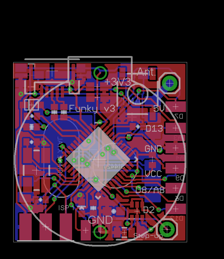
I have made a major reshuffling of the Funky v2, added 8 more pins to the side headers while keeping the form factor. I had to go for ‘pads’ instead of through-hole to make this possible:
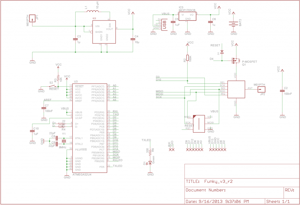
The newly routed pins are D9, D7, D12, D6, A3, A4, D0 and D1; The on-board LED is now moved to another pin (PD5) and the RFM12B enable pin is now D4. The D7 was added as it can be used as analog comparator’s AIN+ input, triggering interrupt on pre-set threshold level. D9 is a PWM pin, D6/D12 can be used as Timer/Counter0(1) Clock Input, A3 and A4 can be used as differential amplifier with up to 200x gain (see atmega32u4‘s datasheet). D0 and D1 are the hardware UART pins, these are routed next to the edge ISP connector.
I have actually received 30 PCBs of the Funky v3 already, but didn’t have time to populate few and toy further.
Pingback: The YAPM PCB is done | Martin's corner on the web
Martin, can you share the Eagle files for Funky v3?