
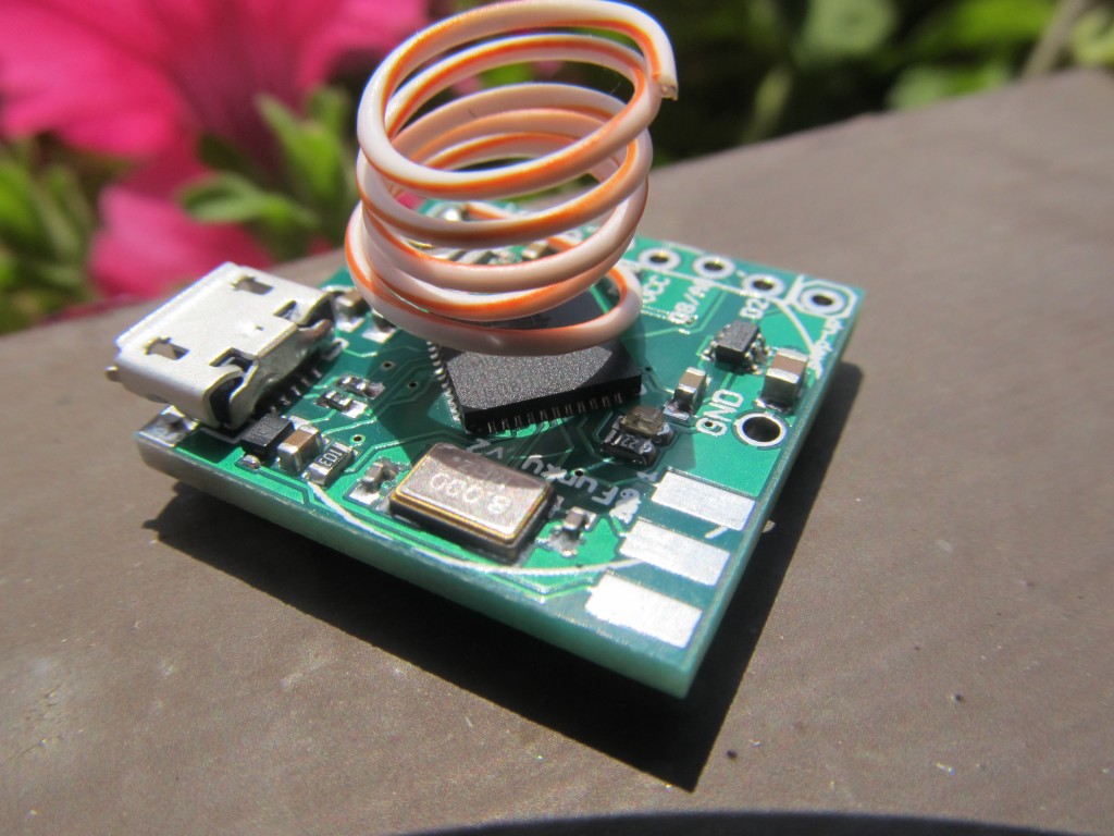
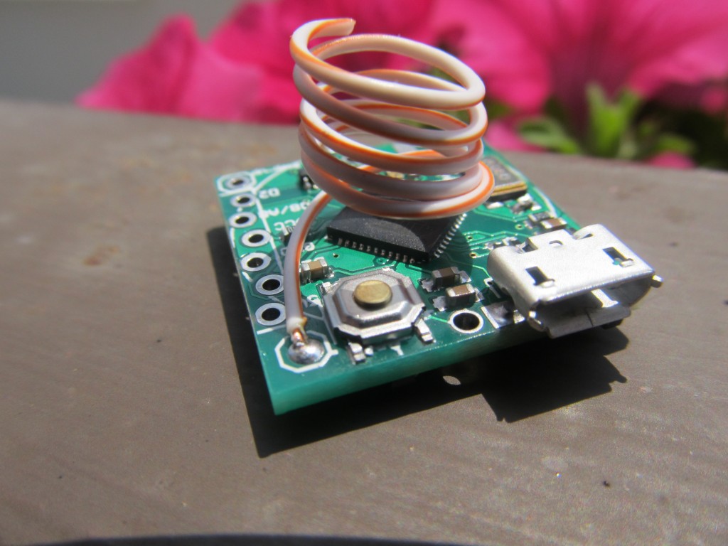
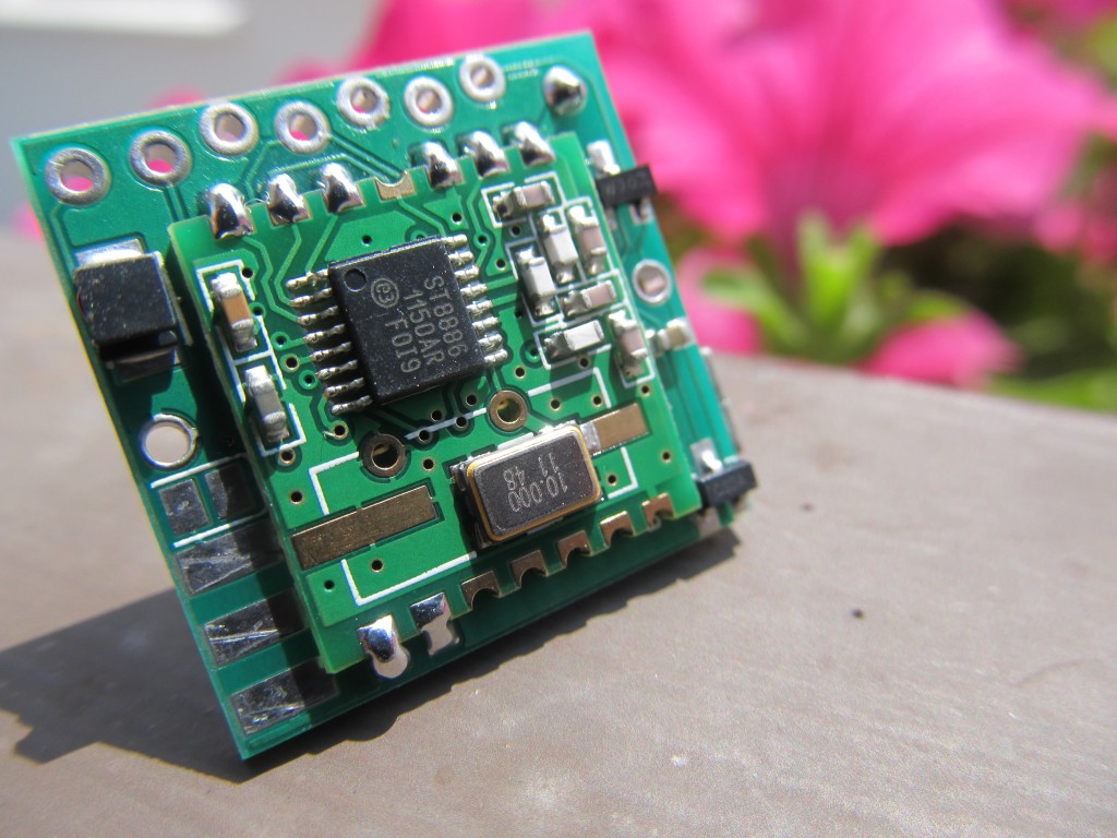
I have made a small improvement to the Funky v2 by adding a reset button to the PCB. The lack of reset button in the previous releases caused some inconvenience when the sketch being run disables USB connectivity (for power-saving purposes), the Funky would become unrecognized by the host system. I was working around this issue by running few lines of code to find out if the Funky is running on battery or USB power, and if running on USB power, I would not disable the USB connection. Now that isn’t necessary, the reset button means you can put the Funky in bootloader mode by a single button press. This makes programming it easier. Some pictures of the new revision:
I have re-stocked few in the shop for those interested in buying one.
This looks really promising for sensor nodes for an Emoncms system. A few questions: 1) I saw that you assemble these yourself. Do you hand solder them, or use an oven? I’ve hand soldered 0603 resistors, etc. but I’m not sure if my hands are steady enough to hand solder the 0402 package size. 2) How do you program the uC using the AVR-ISP-6-EDGE connection with three pads on each side of the board?
Thanks
Hi,
1) I use a hot air gun to do that; if you can do 0603 you will be able to do 0402 – trust me. You just drop the 0402 element ontop the solder paste blob and it will find its way during the reflow process.
2) I use a 2*3 male header with slightly bent pins on one end as interface between the ISP programmer and the edge connector, it is nos soldered, just used while programming. I have pictures of this in the Funky v1 WIKI, check them out
to see what I mean