There is quite some buzz in the RFM12B community recently on low power remote receiver nodes, these are remote, battery-operated nodes that would listen for incoming commands and react to them. The challenge is that keeping the RFM12B powered on all the time eats battery like cheese. There are few ideas floating on how to address that issue, here is a non-comprehensive list
- One option will be to have the remote node wake up at some pre-defined interval and “poke” with a minimum-size packet a central node for instructions. Failing to receive such within a time frame will bring it back to sleep and the cycle will repeat. This particular approach is quite easy to implement, but the draw-back is that there will be no quick way to pass a message from the central node to the remote node, we have to wait until it finishes its nap and asks for data.
- Another approach would be to synchronize transmissions between the nodes – not an easy thing to do, given that a remote node typically has no RTC and its timers become inaccurate while it is sleeping.
- I have been browsing the RFM12b datasheet lately and there is a little explored feature that just begs for testing: It turns out that the RFM module has a wake up timer and a duty cycle register. This means we can precisely define a wake up and for how long the receiver will stay on, listening for the synchronization pattern. If it fails to receive it for the period defined, it will go back to sleep and wake up later to try again. This all happens without waking up the MCU, it only brings the NIRQ line upon valid data being detected.
- The wake-up timer has very low current consumption (1.5 µA
typical) and can be programmed from 1 ms to several days with
an accuracy of ±10%.
The wake-up timer calibrates itself to the crystal oscillator at
every startup. For proper calibration of the wake-up timer the
crystal oscillator must be running before the wake-up timer is
enabled. The calibration process takes approximately 0.5ms.
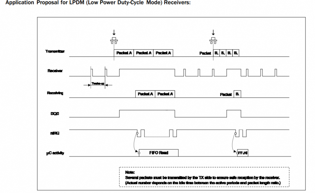
For the crystal start up time (tsx). - In low duty-cycle mode the receiver periodically wakes up for a short period of time and checks if there is a valid FSK transmission in progress. FSK transmission is detected in the frequency range determined by Frequency Setting Command plus and minus the baseband filter bandwidth determined by the Receiver Control Command. This on-time is automatically extended while DQD indicates good received signal condition.
When calculating the on-time take into account:
– the crystal oscillator, the synthesizer and the PLL needs time to start
– depending on the DQD parameter, the chip needs to receive a few valid data bits before the DQD signal indicates good signal conditionChoosing too short on-time can prevent the crystal oscillator from starting or the DQD signal will not go high even when the received
signal has good quality.Here is a good illustration on how this works:
So I think it is worth exploring the last approach, as it is hardware based and probably optimal. Since the wake up timers is calibrated to the crystal, I would think that more precise timing can be planned, i.e. this method can compliment approach 2 outlined above.
The challenge will be to set the the wake up timer and duty cycle just right, so that optimal result can be achieved.
Another challenge will be to measure the effect. I don’t have oscilloscope, so it will be probably measured by just letting a node receive for a while and just see how long it lives.
- The wake-up timer has very low current consumption (1.5 µA


Hello Martin, I’m having some trouble with the high current consumption of my RFM12b. I was doing a little research on how to use this device’s low duty-cycle when I found this post of yours, so I was wondering, did you manage to get it working? Could you give me some tips?
Hi, I never pursued this further. I tried another approach I.e. to reduce transmission power and it works nicely. I have a blog post on the subject. Pls post here if you manage to get the low duty cycle method working, this would be the smarter way to go