As I stalled on porting Jeelib to work with pin-change interrupts on the ATtiny85, I took a different approach and ported an old AVR RFM12 library to work in Arduino IDE as a sketch. I will ideally convert it to a library one day. The good thing about this code is that it uses status polling rather than interrupts and this gives me another pin to use. The cost may be increased power consumption due to active polling between transmitting payload bytes, but I assume it is a minimal difference. Also, I ported the transmission part, I did some work on the receiving code, but not tested it. For a remote sensor I only need transmission mode for now.
So the challenge here was to port the code to be compatible with the packet format used in JeeLib, luckily that is well documented and available here.

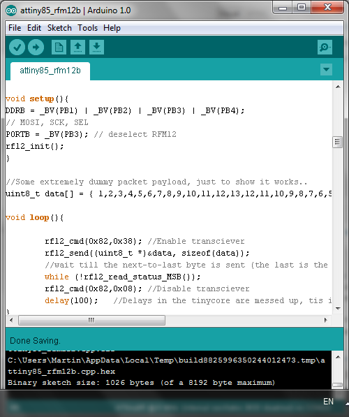
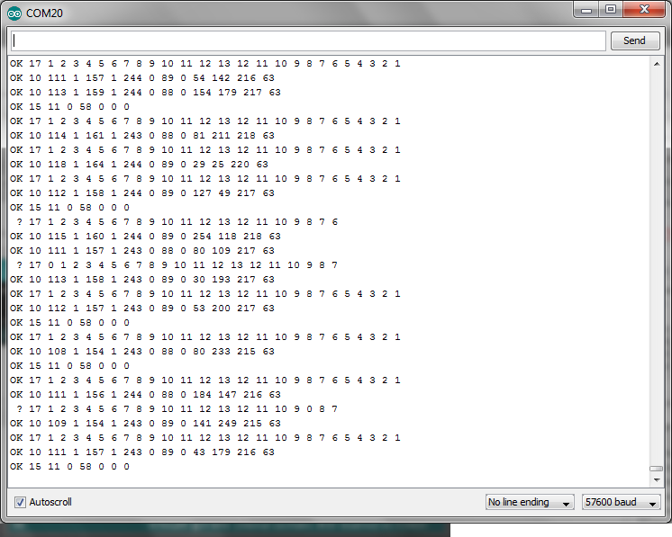
So with a bit of huff-ing and puff-ing I have it working, I am able to send a dummy payload that is picked by a JeeNode running the RF12_Demo sketch. All that from Arduino 1.0 IDE for only 1026 bytes of code..
And finally here is the sketch: attiny85_rfm12b


Will you plan a pcb as for the Attiny84? I can find Attiny85 in eBay but not the Attiny84, so to me this is more great news.
Thank you in advance
I’m not sure yet about the ’85 board, I will decide depending on how my experiments go. I will put the Attiny84’s in the shop too, I have 10+ available
Help! I cant get your sketch working on my Attiny85! I have connected
SS/nSEL on PB3
SCK on PB2
MISO on PB1
MOSI on PB0
and an LED on PB4 to see if it even works.
The LED is blinking but that’s all. I dont receive anything on my other arduino uno where i set up the RF12_Demo…
Swap MISO and MOSI lines, check my schematic carefully and it will work
also make sure you run the Attiny at 8Mhz, 1Mhz is not enough
I tried to switch MISO and MOSI as you said, in code (MOSI_LOW->PB1 & MISO_LEVER->PB0) and in a next try the harware connection. It didn’t work.
I’m using RFM12 (not RFM12B) modules. I’ve already got a working connections between two arduinos using RFM12, Jeelib and code based on the PingPong example.
The RFM12 unit that is now connected to the attiny85 ( 8Mhz internal clock via arduino as ISP) was connected to my Arduino like this:
SCK->Arduino 13 (Attiny85 = PB2)
MISO->Arduino 12 (Attiny85 = PB1)
MOSI->Arduino 11 (Attiny85 = PB0)
CS/SS->Arduino 10 (Attiny85 = PB3)
I have really no clue why it isn’t working. Do you have any suggestions?
What I meant in your first post is that the MISO on the RFM12 should go to what is labeled as “MOSI” on the ATTiny85 and the MOSI on the RFM12 goes to what is labelled MISO on the Attiny85. These are actually DI and DO (data in and data out) pins, lots of people get confused. When programming the Attiny, the pin connections are as you say, but when connecting the RFM12 to the ATTiny make sure MISO from RFM12 goes to PB0 and MOSI to PB1. Another thing to watch out is that I set the RFM group to 210 while RFM12 only suports group 212, you can try to change that in the INIT code, it is in HEX there. pls let me know if you managed.
I tried everything, then i’ve build a new portable circuit with a new 9V LF50CV powerd RFM12+Attiny85. And at least it’s sending something now! But on the receiver side (Arduino with RF12-Demo) this data comes in:
E i5 g212 @ 868 MHz
? 17 1 2 3 4 5 6 7 8 9 10 11 12 13 12 11 10 9 8 7 6
? 17 1 2 3 4 5 6 7 8 9 10 11 12 13 12 11 10 9 8 7 6
? 17 1 2 3 4 5 6 7 8 9 10 11 12 13 12 11 10 9 8 7 6
? 17 1 2 3 4 5 6 7 8 9 10 11 12 13 12 11 10 9 8 7 6
? 17 1 2 3 4 5 6 7 8 9 10 11 12 13 12 11 10 9 8 7 6
? 17 1 2 3 4 5 6 7 8 9 10 11 12 13 12 11 10 9 8 7 6
? 17 1 2 3 4 5 6 7 8 9 10 11 12 13 12 11 10 9 8 7 6
? 17 1 2 3 4 5 6 7 8 9 10 11 12 13 12 11 10 9 8 7 6
? 17 1 2 3 4 5 6 7 8 9 10 11 12 13 12 11 10 9 8 7 6
(my mobile RFM12 has network group 212 and Node-ID (Header) 17)
What make my data corrupt?
Thank’s for the help till this point anyway!!
From what I can tell is that the receiving side is showing corrupted CRC (the ? in the begining of the message). Also the message seems truncated, it should go down to 1, while it stops at 6 from what you posted. can you try to send a smaller packet, maybe 5 bytes. You are really close to getting it right.
It’s finally working perfect!!
I’ve added the packet size(25) of *data as byte nr.1 and a counter of the sender as byte 2.
OK 17 25 1 3 4 5 6 7 8 9 10 11 12 13 12 11 10 9 8 7 6 5 4 3 2 1
OK 17 25 2 3 4 5 6 7 8 9 10 11 12 13 12 11 10 9 8 7 6 5 4 3 2 1
OK 17 25 3 3 4 5 6 7 8 9 10 11 12 13 12 11 10 9 8 7 6 5 4 3 2 1
OK 17 25 4 3 4 5 6 7 8 9 10 11 12 13 12 11 10 9 8 7 6 5 4 3 2 1
OK 17 25 5 3 4 5 6 7 8 9 10 11 12 13 12 11 10 9 8 7 6 5 4 3 2 1
OK 17 25 6 3 4 5 6 7 8 9 10 11 12 13 12 11 10 9 8 7 6 5 4 3 2 1
OK 17 25 7 3 4 5 6 7 8 9 10 11 12 13 12 11 10 9 8 7 6 5 4 3 2 1
OK 17 25 8 3 4 5 6 7 8 9 10 11 12 13 12 11 10 9 8 7 6 5 4 3 2 1
OK 17 25 9 3 4 5 6 7 8 9 10 11 12 13 12 11 10 9 8 7 6 5 4 3 2 1
The calculated CRC in the original code was wrong. In the void rf12_send (..) function i had to replace:
rf12_TX(GROUP); //SYNC LOW BYTE (group 210)
chksum = _crc16_update(chksum, 0xD2);
by
rf12_TX(GROUP); //SYNC LOW BYTE (group 210)
chksum = _crc16_update(chksum, GROUP);
Now i can send packets in the size of my choice! THANKS for the help!!
Great 🙂 I’d be interested to see your project when it is ready, please post a link
Pingback: Using ATtiny 84′s internal temperature sensor | Martin's corner on the web
For those desiring a minimal implementation, check out http://www.kickstarter.com/projects/digistump/digispark-the-tiny-arduino-enabled-usb-dev-board . This is a kickstarter for a VERY small (<1 sq in) arduino implementation with an attiny85. There is an available 'shield' for a RFM12B, so this may be a perfect platform for a minimum configuration.
Personally, I don’t understand all the hype that goes with the digispark. I think the ‘Funky’ is much more powerful (AtTiny84 based) plus has step-up circuit plus can operate on a CR2032 battery plus already has RFM12B. More than perfect for low-power wireless node.
Got this sketch working after modifying the crc line as described above (found out the hard way). I also connected DS18B20 sensors to the unused PB4 and now i can get accurate temperature measurements using the OneWire and DallasTemperature libraries.
I’m wondering if anyone has a code snippet describing how to get bandgap voltage reading from Attiny85?
How you did it? For 1-Wire i need to lines…?
You need GND and a data line as a minimum in the “parasite power” mode, so it i perfectly possible
If using DS18B20 in parasite mode you need to connect the sensors power pin to GND and pull the data pin up to VCC with 4,7k resistor. DallasTemperature library detects the parasite mode and holds data pin high for some time before actual data tranmissions to charge the sensors internal capacitor.
Hi Ull,
Is it possible to send to me your plans and your sketches ?
i try to make to heating centralisation with wireless sensors
thanks
Regards
I really like this project. Good work! I’ve been looking at making a wireless temperature sensor and came across both your site and jeelabs. And of course that means I have questions. Is there a particular reason you like using the RFM transceivers? I’ve been looking at the rf-2400 transceivers, they are much cheaper and they look like they could also work. What are your thoughts on this? With the funky board is the reason for the voltage step up circuit for allowing different kinds of voltage sources? If you always used 2 AAs at 3V would you need the step up circuit?
It is probably just the habit, I too don’t like much the RFM12b, but all of my house is already bugged with these.
The reason for the step-up is to provide steady 3.3V that some sensors need, for example the DHT22; two AAs will at some point drop below 3V and make the sensor useless.
I’m trying to build a similar project using some cheap NRF24L01. From what I read, 2.4 Ghz devices can have higher transmission rates than 430/900 Mhz but are worse for penetrating walls (which is still fine for house monitoring but may not be up to the job when monitoring bigger sites). They are also supposedly more energy efficient than RFM12B but I still have no experience with them. I’ll definitively give some feedback to Martin about my experience.
Best regards,
RexCortex
Hi Martin,
awesome project!
I wanted to use an ATTiny85 with an WS2811 and an RFM12B to make some kind of remote controlled RGB LEDs. I got the ATTiny85 with the WS2811 already working by using the (Analog Input 2) / PIN 4 of the ATTiny85. I only want to transmit an id, the mode changes (autonomous mode/controller based mode) to the ATTiny as well as RGB Information, so about 5 times 1 byte in max (i.e. ID,Mode,Red,Green,Blue\n or 42,0,0,0,0\n or 42,1,255,255,255\n). Does that work? Can i somehow get my ATTiny85 to just recieve data your way (with only using the 4 pins left I got on my ATTiny) and use it that way to controll the LED?
Thanks a lot!
Hi,
interesting; I’d rather go for the Attiny84 and take advantage of the available libraries (JeeLib); This particular experiment was intended as sending-only; The code should be pretty easy to adapt for receiving too, that part is there already, but I never tested it.
Cheers
Thanks a lot!
Do you know of anyone who maybe tested it already?
I would have to manufacture multiple of the nodes, so an smaller mcu and smaller price point would make it more affordable.
Do you think the RFM12B would be suitable for my kind of project, or would you think of another Radio Module?
And can I wire the Module directly to the Tiny85/84 (given that it is running on 3,0 – 3,3V) or are there some other parts needed?
Thanks a lot, and thanks for providing this blog and infos!
Hello,
I’m trying to run attiny85 with rfm12b.
I’ve added all stuff to rfm12b according to this ( http://forum.jeelabs.net/node/1205).
Then fired Your sketch from above link – and nothing comes through.
But when i fired Your demo sketch from this page – it started to work.
Can You tell if it problem with rfm12b initialization, or maybe sending function?
Thanks!
Hi, both posts are mine,
the one on jeelabs is when I was asking for help to get Jeelib going on ATTiny85; I could not make it work. So I took alternative route and managed to get it going with different code.
This looks SOOO close to what I need. I’m in the US and am using the 433MHz version of the RFM12B. What do I need to change to adapt for the different frequency?
Also, I’d love to get this to work with the Adafruit Trinket. It’s a nice little package and easy to program. Any idea whether this would work with the Trinket and what needs to change to make it work?
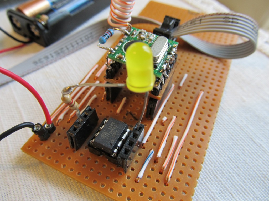
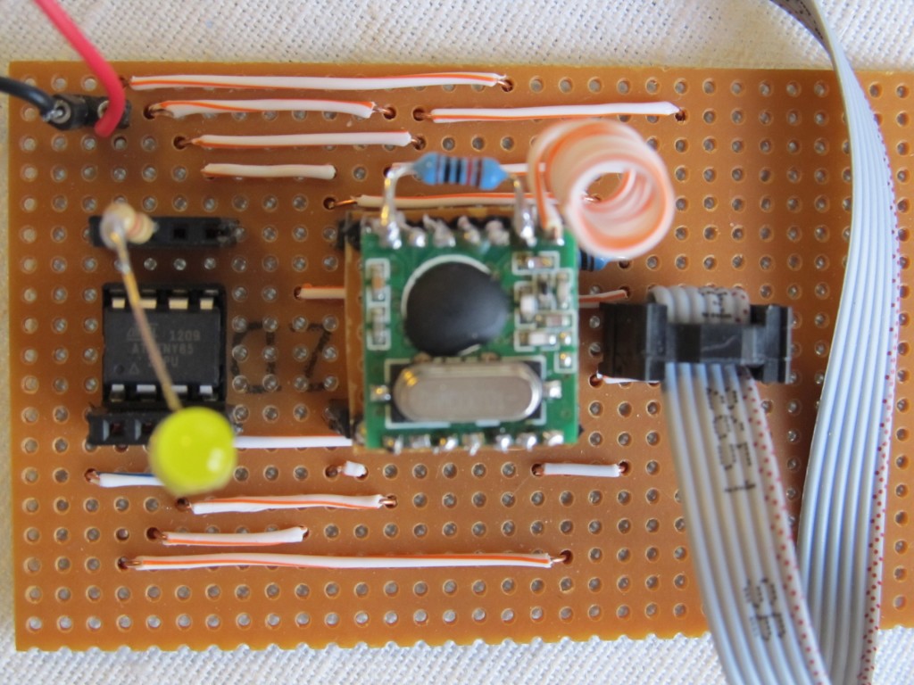
Is there a link to a more clear wiring diagram than the JPG of the perfboard? I did see the schematic of the wiring from the original attempt at the software, but to be honest, don’t understand the notation. (http://forum.arduino.cc/index.php?topic=110182.0) In that notation, do I tie together like indications, such as PB0’s all tie together, PB1’s all tie together, etc?