
I did some range testing earlier today, using a ping-pong pair of sketches uploaded to a WorkerB! and a Dirt Cheap Low Power Wireless Sensor Node:
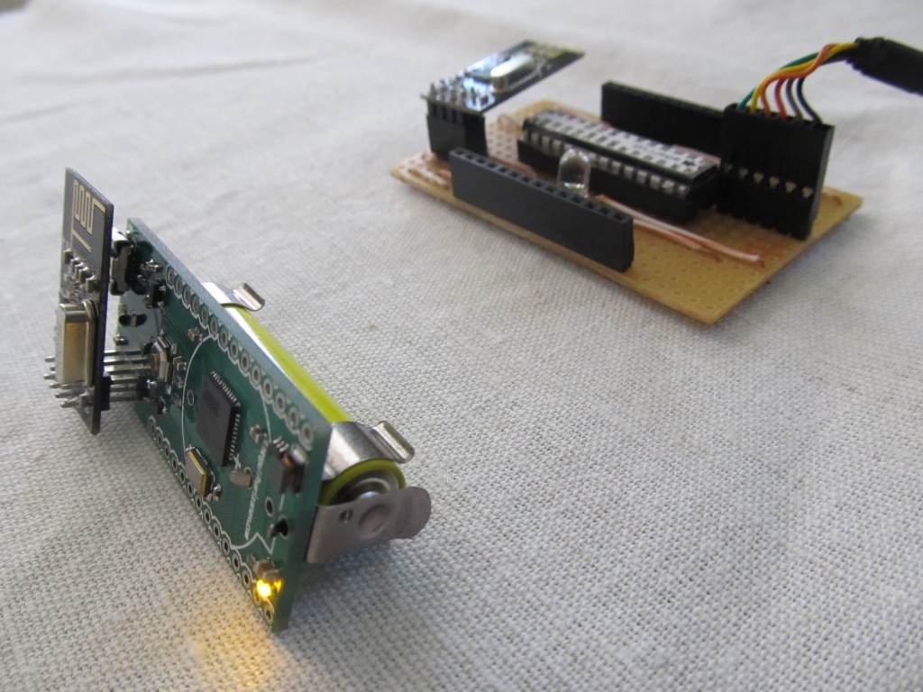
This works by sending an incrementing value (millis’ value) every second, and the client picks it up. When picked up, the client will light its LED for few ms so that it is visible. I took the battery operated WorkerB! and moved around to see how its reception varies. Range is comparable to that of the RFM12B, i.e. covers most of the house. There are some spots where I don’t get signal, moving 30 cm to the side would sometimes resolve it. This will be useful when actually deploying nodes, picking up a good location will mean less lost transmissions.
I did an outside test and it would easily work over 40m distance with straight line of visibility.
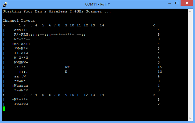
When doing these tests, I did a 2.4Ghz scan to check for free channels (stay out of WiFi interference)
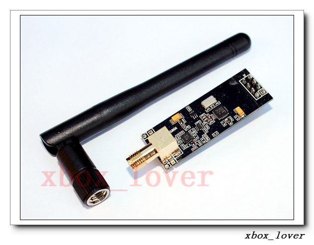
There is a pin compatible version of the nRF24L01+ sold on eBay of this module with a PA+SMA antenna, that claims a 1KM range, this could be used as a gateway to pick up the transmissions from the remote nodes, I may get one of these to try out too:
EDIT: Below is a quick+ugly+out of scale house plan with a reception legend for floors 1 and 2. The sending node is the purple square in the dining area, it is not in the center of the house so some areas are not covered. I have recorded with colored stars the reception inside and outside the house; Green star indicates excellent packet receipt. Orange indicates some missed packets. Changing the orientation of the receiving node or moving it slightly improves the reception. Red star indicates unacceptable or missing coverage. I walked in the garden around the house so floor 1 plan has some of the stars outside the house:

Floor 1

Floor 2
In my permanent setup, the Internet router and my IoT gatway are located under the stairs, so hence in the center of the house. The coverage is excellent this way, so it is important to find a good location of the gateway so that it is centrally located to th remote nodes
I’m pretty happy with the range of the module
So, what is the range inside the house, through concrete floors and walls? How does it compare with an RFM12B, that has an line-of-sight range of at least 500m?
The house is concrete, that causes some trouble. I added couple hand-drawn house plan and reception legend to the post, take a look.
I can say that basically the RFM12 nodes I have have same reception, probably the default settings that I used aren’t optimal.
Nice graphics!
I recently started playing with the nRF24L01 transceivers just a couple of weeks ago and found your blog in search of more information about working with these wonderful little devices. It’s funny that you posted this today as I did some preliminary range testing just last night with nearly identical results. I also placed an eBay order for one with an external antenna. I’ll give it a try with the standard antenna, but I also have some larger antennas (antennae?) that are 20″ and 22″ tall that I will try as well. It will probably be 2-3 weeks (minimum) before the new transceiver arrives from China, but I will report back with my findings!
By the way, I love the frequent updates, especially in regards to the sensors, energy harvesting, and wireless stuff! I’ve been tinkering with all of these off and on over the years, but I’ve never really made any progress until now.
Thank you!
funny output, where I can get a description of what it mean ?
regards
can use the ping delay to calculate the distance to trransmisor?
thanks! 🙂
not really. sometimes a larger delay only means the initial transmission didn’t go through and the unit had to re-transmit
This weekend I did some range testing with these nRF24L01+ modules myself. In the appartment building I live in two standard modules penetrate two heavy concrete floors. If I dremel-off the PCB antenna on two modules and solder on a wire antenna (coiled or straight) the signal goes through three floors and when I replace another module with a PA/LNA module that goes up to four floors (reliably).
That’s interesting, thanks for sharing! Gotta try it some day
how long should the wire be for 2.4Ghz?
“dremel-off the PCB antenna on two modules and solder on a wire antenna (coiled or straight)”
Can you provide a picture of what you did? I’m very new to this. I’m just imagining that you scratch the antenna trace (the zig zag lines) off the PCB board and just solder a 3 inch length of wire to it? That that sound right?
I made the wire 3/4 wavelength (about 9.2 cm). But I’m not really an antenna/electronics engineer, so it may not be the best choice. One disadvantage I noticed by now is that it is quite easy to tear off the PCB trace where the wire is soldered when youŕe not careful.