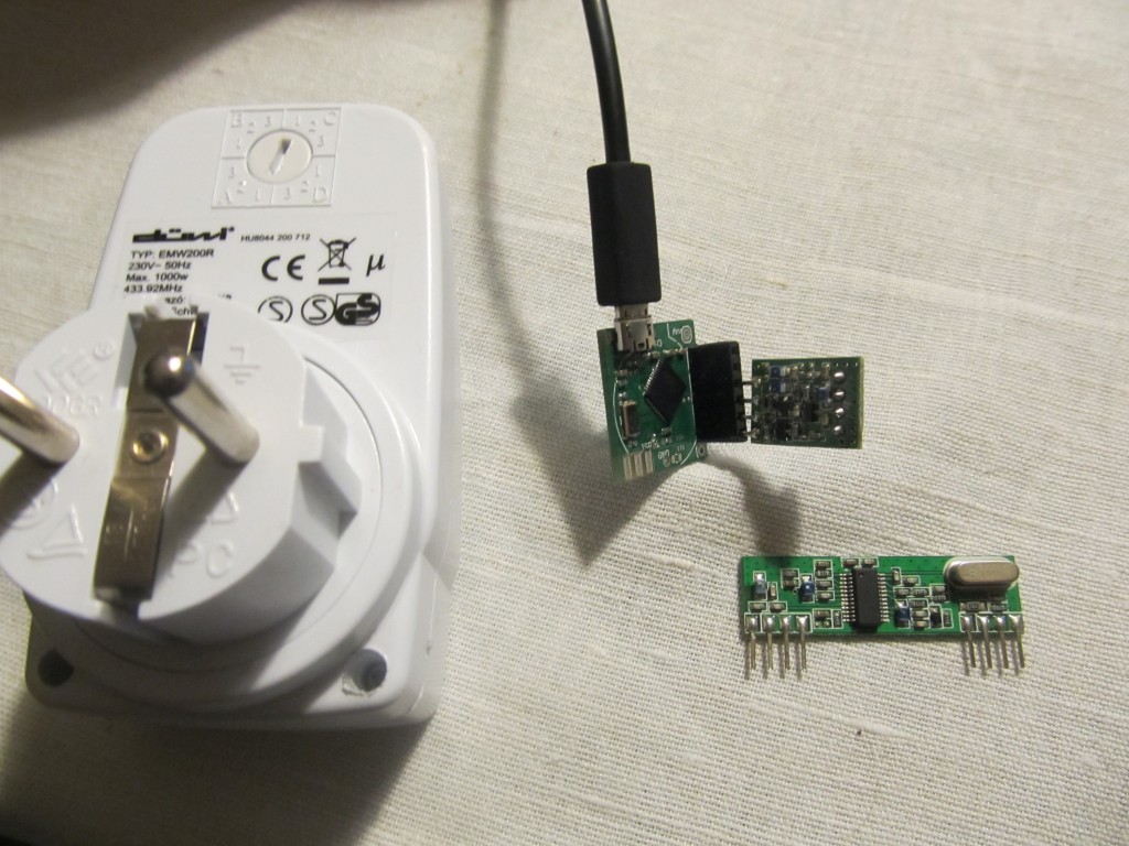
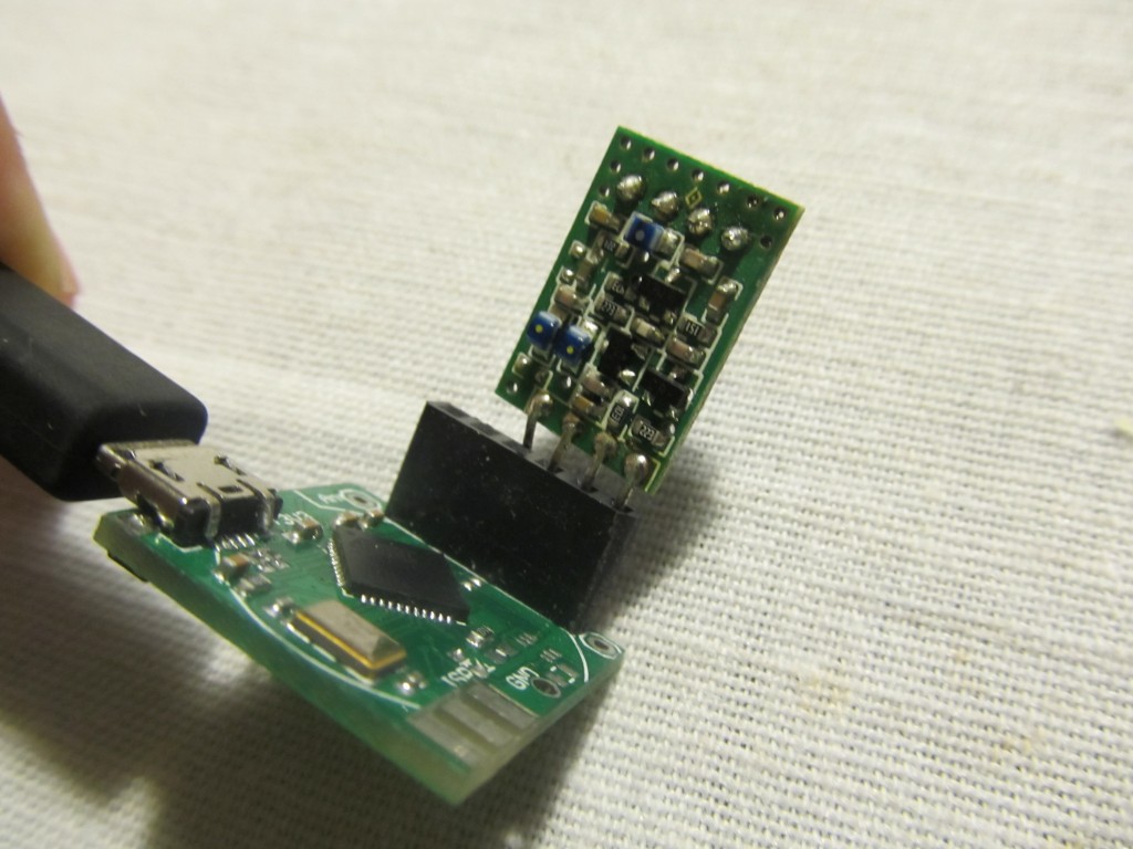
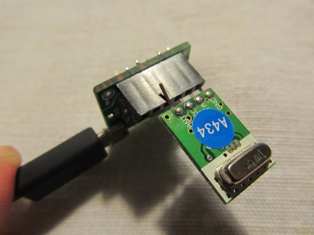
Here is a 15 minute project: control 433Mhz RF sockets with the Funky v2: I have a 433Mhz OOK transmitter/receiver, I don’t even recall where I got them. These are widely available on ebay for less than $5 delivered. I used FuzziLogic’s 433Mhz Arduino library for the purpose. First I wired the receiver on a breadboard and used the ShowReceivedCode example to get the period and codes for ON / OFF for House A, application 1. Then I used the so received code and period value to send is as raw data telegram using this simple sketch:
#include <RemoteTransmitter.h>
//https://bitbucket.org/fuzzillogic/433mhzforarduino/

RemoteTransmitter RemoteTransmitter(A0,323,8);

void setup() {
  //See example Show_received_code for info on this
pinMode(A0, OUTPUT);
pinMode(2, OUTPUT);
digitalWrite(2,LOW);
}

void loop() {

  unsigned long code;
  unsigned long receivedCode;
  unsigned int period;

 //Used this sketch to read the code: https://bitbucket.org/fuzzillogic/433mhzforarduino/src/edabcd754f5b/RemoteSwitch/examples/ShowReceivedCode/ShowReceivedCode.ino?at=default
  receivedCode=172771;
  period=323;

  //Copy the received code.
  code = receivedCode & 0xFFFFF; //truncate to 20 bits for show; receivedCode is never more than 20 bits..

  //Add the period duration to the code. Range: [0..511] (9 bit)
  code |= (unsigned long)period << 23;

  //Add the number of repeats to the code. Range: [0..7] (3 bit). The actual number of repeats will be 2^(repeats),
  //in this case 8
  code |= 3L << 20;

  RemoteTransmitter::sendTelegram(code,A0);

  //Wait 5 seconds before sending.
  delay(5000);

  receivedCode=172770;
  period=323;

  //Copy the received code.
  code = receivedCode & 0xFFFFF; //truncate to 20 bits for show; receivedCode is never more than 20 bits..

  //Add the period duration to the code. Range: [0..511] (9 bit)
  code |= (unsigned long)period << 23;

  //Add the number of repeats to the code. Range: [0..7] (3 bit). The actual number of repeats will be 2^(repeats),
  //in this case 8
  code |= 3L << 20;

  //Retransmit the signal on pin 11. Note: no object was created!
  RemoteTransmitter::sendTelegram(code,A0);
  delay(5000);

}
Works as a charm, switching the power socket on and off every 5 seconds. I find this approach much safer and less intrusive compared to wiring relays. Since the Funky v2 acts as a virtual serial CDC device, it is really easy to control RF switches from serial of a laptop/Raspbrry Pi too. I didn’t wire an antenna, but even without one I get 3m range.
P.S. This blog makes 1 year today 🙂


Hello
Is it also possible to switch power sockets with the RFM2Pi or the TinyTx-Boards??? Some German guys made it with the RFM12B module But I am not a programming professional. Their code is too complicated for me. Have you ever tried to switch the sockets with the RFM2Pi???
The current version of the RFM2Pi board is limited in RAM, so It will be hard to do while keeping the default firmware in too.
I have done that with an Arduino: see here
Thanks for the Link. I tried the other code on my attiny84 with rfm12b (tinytx-Board). It does not run for now but i give it another try tomorrow. Maybe the Code for my Powers sockets are different. I will see it Tomorrow
I finally did it. 🙂 I used the code from http://talk.jeelabs.net/topic/407
(6th comment from Top)
It seems nearly the same as yours but the timings are a litte different.
Thank you for your help.