
With the winter heating season knocking on the door, I decided to measure the room temperature in every room in the house. The Funky is perfect for the purpose, as a DS18B20 temperature sensor can be soldered directly on its pads 4,5 and 6. I have provisions for a 4.7K resistor between pads 4 and 5, so it is just a matter of one minute solder job. The DS18B20’s flat body part must point towards the side where the RFM12B lays:


You can connect several of the temperature sensors to one Funky, the code will recognize two at most (this can easily be changed to more than two).
Here is the code that I am running. It reports room temperature every 5 minutes.
Rough calculations give me more than 220 days of usage before the CR2032 battery dies.
[edit] I am adding a live chart so anyone can monitor the battery life for this project; Fresh battery inserted on Nov 1st 2012; the chart will reload on page refresh:
Funky+DS18b20 on a CR2032
The battery discharge pattern follows the expectations, note the strange fall and then slight rise in voltage:
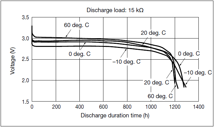
CR2032 discharge profile
I also decided measure the room temperature in every room in the house. My idea: Master funky should have LCD displaying temperatures from all room funkys.
My questions:
1.) What is the limit of cables length from funky to DS18B20 sensor?
One DS18B20 is soldered directly to funky, another DS18B20 is measuring temperature in second room. Where to connect another DS18B20 ?
2.) How do you display temperatures from funky sensors ?
Tip for you:
MSPNode instead of Jeenode. ATMEL mcu is replaced with Texas Instruments value line (low power consumption) MSP430 chip. RF chip is the same – RFM12B.
Limitations: lower baud rate, not all library functions are available (porting of JeeLabs protocol/rf12 library v2 from ATMEL to TI MSP430 value line chips ).
http://norduino.robomotic.com/mspnode-is-born/
http://www.norduino.org/index.php/MSPNode_board
I have a 3 meter cable at home for monitoring my solar heater up the roof, I haven’t experimented with greater lengths than that, but from looking up on the internet something like 6-10 meters seems to be the limit.
The DS18B20s share the same bus, you can connect few of them on the same pins and the sketch recognizes them by their unique ID.
Regarding displaying data: you may want to store and analyse the data over some period, I use http://openenergymonitor.org ‘s emoncms. If that is the case, you can use a emonBase (a Nanode), look it up on the same site. If you own a RaspberryPi, you can use my RFM2Pi board, also available in the store. In case you just need to visualize the data, use emonGLCD (again from openenergy). You can also do it quite cheap by hooking a Serial LCD, just mind to hook the TX only as the Funky is 3.3V (most serial LCDs are 5V BUT will take 3.3V logical levels as RX, so the Funky can feed it with data to display)
Hi Martin,
really fantastic work. Since i received my Pi this Sensor was haunting me. I installed emoncms on the Pi plugged in homemade RFM2Pi board with flashed ATTiny84 and started building your FUNKY hardware. So i built up a board on a test shield. Started compiling your code in Arduino 1.02 and bang. Nearly one page of Errors. Phew. Checked the libs. Downloaded them new. Jeelib, OneWire and the Dallas thing. Checked the processor. ATTiny84 @ 8Mhz (internal oscillator; BOD disabled). Compiled again. Same result, Lots of Errors. Nothing helped. So i hope that you can give me some info. Am i using the right Arduino IDE version.
Thank you.
Hi,
I assume you have seen my comments on setting up the Arduino IDE here:
http://harizanov.com/2012/08/setting-up-arduino-ide-for-working-with-attinys/
If none of these tips help, post the error you get. Maybe it will ring a bell.
Thanks for the reply Martin,
i followed setting up the Arduino IDE and everything is working perfect with that. I have already made some ATTiny84 / 85 boards for several applications and they work very good. I never used the Jeelib and the Softserial modules. Mainly the boards are used as remotes.
To start with a new project i downloaded the RFM2Pi-master software and burned the ATTiny84 with the ATTiny84_RF12_Demo.cpp.hex and installed it on the PI. Next i downloaded the ATTiny Sensor software as you have a lot of examples in it. I thought i could run some samples to see how everything works before i connect to the Pi. So i compiled the RF12Demo for Attiny84_RFM12b. The result was also stocking. Here are my errors:
/Applications/Arduino102.app/Contents/Resources/Java/hardware/tools/avr/bin/../lib/gcc/avr/4.3.2/../../../../avr/lib/avr25/crttn84.o: In function `__vector_default’:
(.vectors+0x2): relocation truncated to fit: R_AVR_13_PCREL against symbol `__vector_1′ defined in .text.__vector_1 section in core.a(WInterrupts.c.o)
/Applications/Arduino102.app/Contents/Resources/Java/hardware/tools/avr/bin/../lib/gcc/avr/4.3.2/../../../../avr/lib/avr25/crttn84.o: In function `__vector_default’:
(.vectors+0x16): relocation truncated to fit: R_AVR_13_PCREL against symbol `__vector_11′ defined in .text.__vector_11 section in core.a(wiring.c.o)
/Applications/Arduino102.app/Contents/Resources/Java/hardware/tools/avr/bin/../lib/gcc/avr/4.3.2/../../../../avr/lib/avr25/crttn84.o:(.init9+0x0): relocation truncated to fit: R_AVR_13_PCREL against symbol `main’ defined in .text.main section in core.a(main.cpp.o)
/Applications/Arduino102.app/Contents/Resources/Java/hardware/tools/avr/bin/../lib/gcc/avr/4.3.2/../../../../avr/lib/avr25/crttn84.o:(.init9+0x2): relocation truncated to fit: R_AVR_13_PCREL against symbol `exit’ defined in .fini9 section in /Applications/Arduino102.app/Contents/Resources/Java/hardware/tools/avr/bin/../lib/gcc/avr/4.3.2/avr25/libgcc.a(_exit.o)
TinySensor_RF12_Demo.cpp.o: In function `saveConfig’:
/Applications/TinySensor_RF12_Demo.ino:82: relocation truncated to fit: R_AVR_13_PCREL against symbol `Print::println(char const*)’ defined in .text._ZN5Print7printlnEPKc section in core.a(Print.cpp.o)
TinySensor_RF12_Demo.cpp.o: In function `showString’:
/Applications/TinySensor_RF12_Demo.ino:106: relocation truncated to fit: R_AVR_13_PCREL against symbol `Print::print(char, int)’ defined in .text._ZN5Print5printEci section in core.a(Print.cpp.o)
/Applications/TinySensor_RF12_Demo.ino:107: relocation truncated to fit: R_AVR_13_PCREL against symbol `Print::print(char, int)’ defined in .text._ZN5Print5printEci section in core.a(Print.cpp.o)
TinySensor_RF12_Demo.cpp.o: In function `showHelp’:
/Applications/TinySensor_RF12_Demo.ino:113: relocation truncated to fit: R_AVR_13_PCREL against symbol `Print::println(char const*)’ defined in .text._ZN5Print7printlnEPKc section in core.a(Print.cpp.o)
/Applications/TinySensor_RF12_Demo.ino:132: relocation truncated to fit: R_AVR_13_PCREL against symbol `Print::print(int, int)’ defined in .text._ZN5Print5printEii section in core.a(Print.cpp.o)
/Applications/TinySensor_RF12_Demo.ino:133: relocation truncated to fit: R_AVR_13_PCREL against symbol `Print::print(char const*)’ defined in .text._ZN5Print5printEPKc section in core.a(Print.cpp.o)
/Applications/TinySensor_RF12_Demo.ino:134: additional relocation overflows omitted from the output
After that i tried to compile the the software from the RFM2PI-master firmware and had the same result.
What am i doing wrong? It would be very kind of you to give me some help.
hmm, this is exactly the issue I describe in item 4 of my “Setting up Arduino IDE” post. I got that too, it was easy to fix following the link provided. I did that on Arduino 1.0.1 though.
Okay i’ll download Arduino 1.01 and try all again. By the way i used Arduino-tiny-100-0015. Made all the possible changes.
Inserted this in ports.h:
// keep the ATtiny85 on the “old” conventions until arduino-tiny gets fixed
#if ARDUINO >= 100 // && !defined(__AVR_ATtiny84__) && !defined(__AVR_ATtiny85__) && !defined(__AVR_ATtiny44__) && !defined(__AVR_ATtiny45__)
#define WRITE_RESULT size_t
#else
#define WRITE_RESULT void
#endif
* Start the Arduino IDE and ensure there are two new boards listed under the
[Tools] [Board] menu…
“ATtiny84 @ 8 MHz”
“ATtiny84 @ 1 MHz”
There is nothing like this in my directory
If you don’t see the attinys in the boards menu, then you haven’t set up the Tiny core correctly. double check that step.
After you see these two, you know that you did it right.
Sorry i was wrong i surely do have a boards menu and can select a Tiny board. I have selected “ATTiny84 @ 8MHz (internal oscillator; BOD disabled).
Now i have tried Arduino-Tiny-0100-0013 to 0015 with Arduino IDE rc2, 1.01 and 1.02. I made all changes. But still only a lot of errors. Any other chance to win this game?
Okay now i downloaded the complete jeelib packet and compiled the RF12Demo as it is and wonder o wonder it compiled. I changed the ports and still it compiles. I am going to plug this chip on the Pi shield and look what it answers.
Hi,
I think your modified version is exactly what I need to monitor my temperatures but before ordering I would like to understand one thing.
The units are broadcasting values over radio, right ? But how can I collect them on my raspberry Pi ?
Thanks
Hi,
see the RFM2Pi board: http://harizanov.com/2012/10/rfm12b-to-raspberry-pi-board/
It is also available in the store.
Hi Martin,
These funky sensors are really incredible!
While waiting for the new arduino compatible ATmega version, I’m trying to build my own ones for testing purpose. I was wondering how the DS18B20 was working with low voltage over lifetime with coin bat. Typically, a CR2032 has 3V when fresh and 2.8V at 3/4 of its lifetime and the voltage range of DS18B20 is supposed to work within voltage range of 3V-5V. Is the DS18B20 solution only viable with the voltage step-up?
Thanks!
Excellent question that had bothered me for a long time. The plain ‘Funky’ (with no step-up) that I describe in this post got a brand new “Sony” battery on Nov 1st 2012 and here is how it has been behaving for the last 3 months with that same battery:
It is visible that the battery level depends on the room temperature, we were away for couple days in January and that is clearly visible on the graph.
I report room temperature every 5 minutes with no ACK; the code is so energy efficient that I expect another at least 3 months before the battery dies. I will definitely make a blog post when that happens so that everyone is aware.
So it seems that the DS18B20 does work with voltages below 3V, my experience so far shows they start misbehaving at around 2.7V
Thank you for your very detailed answer! I will try to use a Arduino Mini Pro 3.3V as a sensor with a coin cell. Though I’m not sure if I can achieve such great energy efficiency with an ATmega328.
I’m looking forward to your updated funky! Best regards.
Pingback: Power saving techniques on the Atmega32u4 | Martin's corner on the web
Pingback: JeeNode setup | DTU – Cold Chain Logistics
Pingback: Using my 1.8 TFT as a Raspberry Pi status display | Martin's corner on the web
I have been doing some analysis of the DS18B20’s power consumption using my newly acquired µCurrent (love it) and there are some tricks to make the DS18B20’s use less power (on an Uno at least). Sitting idle doing nothing at all they consume 1.547 µA powered at 5V but only 1.160 µA powered at 3.3V. There is an even larger different during SPI communications. I measure 22.7 µA @ 3.3V during constant dialog via SPI (I mean my loop is really hammering it) but 60.0 µA @ 5.0V running the same loop. Obviously there is no point powering these little things at 5 volts when 3.3 works just fine and saves 387 nA less sitting idle and 37.3 µA less during communication and temperature conversion.
Another trick is to power them off a digital pin and bring it low during sleep. Obviously this cuts power consumption to zero during sleep. There does not seem to be any lag whatsoever in bringing the pin high and issuing commands. My sensors work as expected immediately after bringing the pin high and issuing a convert temperature command.
Chris, I power mine from a digital pin; For true low-power a DS18B20 is an overkill as it takes quite a while to measure the temperature. A TMP36 would basically do the same job for much less time and thus prolong battery life.. but anyway who cares when this thing is running for 5 months already on a button cell battery
I’ve also had real success turning the clock speed of my Uno *way* down in order to hold the tedious and length SPI communications with my DS18B20. Obviously I want to “sprint to the finish” but we are stuck with long 60µs time slots when talking back and forth with the DS18B20 so we might as well turn the processor as slowly as possible during this time. It takes 2-3ms to request a temperature reading and 8-11ms to read the result back. I can use a clock divider of 32 and still communicate with the temperature probe. Anything slower than that and I can’t get the serial output back out of my Uno.
Pingback: Thomas Höser » 1.8 TFT Raspberry Pi status display
Pingback: CR2032 battery discharge pattern | Martin's corner on the web