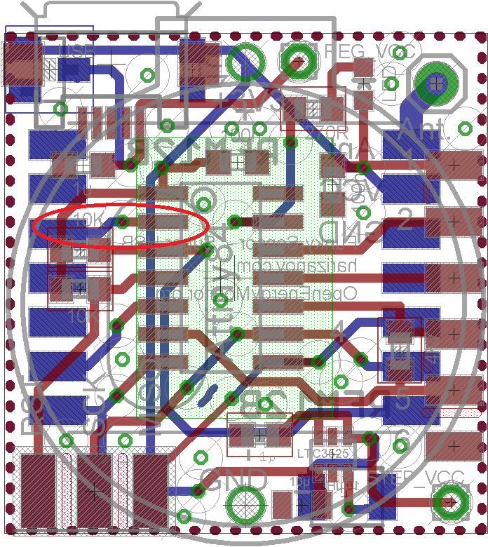
I have already expressed my thoughts on this, and of course could not resist materializing them. The main reason is that I would like to experiment with IR and RF stuff that requires precise timings. The internal oscillator’s frequency depends notably on temperature and voltage change and although it can be calibrated, I still prefer crystal. The Funky is already small enough to fit another crystal so the only logical solution would be to use RFM12b’s CLKOUT. I have connected RFM12B’s clock out pin to ATTiny84’s CLKI pin on the latest Funky sensor, it happens to be quite a short track anyway, so good for keeping interference to minimum:
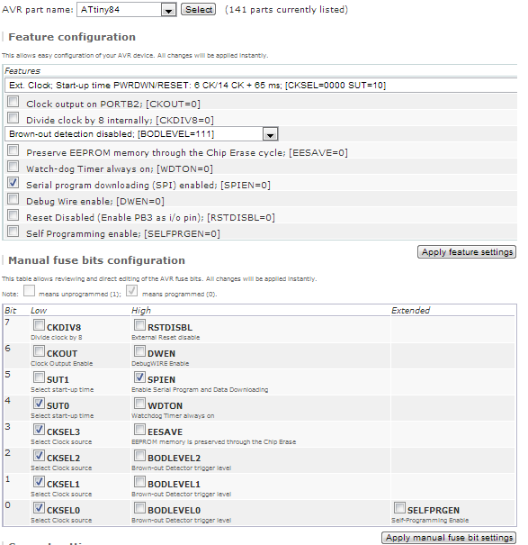
This is entirely optional to use and can be enabled through ATTiny’s fuses. Using the AVR fuse calculator, I got the correct fuse values:
Setting them is easy:
avrdude -c usbtiny -p t84 -e -u -U lfuse:w:0xe0:m -U hfuse:w:0xdf:m -U efuse:w:0xff:m
This instructs the ATTiny84 to be clocked from external clock and not the internal oscillator.
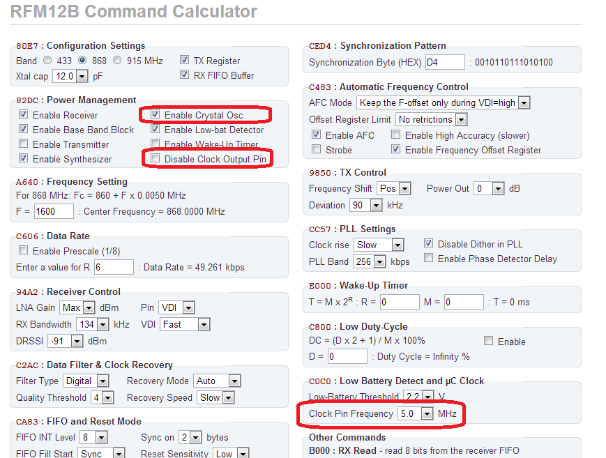
Next, I looked up on how to drive the CLKOUT pin on the RFM12B. Jeelab’s jeelib disables CLKOUT on RFM12B first thing upon calling rf12_initialize, so that called for changes. I have looked up the RFM12B command using Jeelab’s calculator, and identified the necessary changes:
Basically Jeelib keeps the CLKOUT disabled, and I had to make sure this doesn’t happen or our MCU will hang clock-less. Another thing to watch out is the “Enable crystal osc” setting, we need that on at all times. So these observations resulted in modifying the RF12.cpp file and re-define the following commands as follows:
// Update RF12 command codes so that they don't mess CLKOUT and Crystal osc
#define RF_RECEIVER_ON 0x82DC
#define RF_XMITTER_ON 0x823C
#define RF_IDLE_MODE 0x820C
#define RF_SLEEP_MODE 0x820C
#define RF_WAKEUP_MODE 0x820E
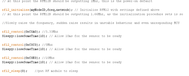
Then I wanted to specify the frequency to be output to RFM12’s CLKOUT pin, this must be done gradually or the Tiny misbehaves:
So with these small modifications, I now have externally clocked Funky . Running the Funky off crystal would mean reduced power efficiency, however I have provisions for micro USB powering and voltage regulator on the PCB, so powering the Funky from the grid or LiPo battery is possible.


Will you try your “64 800 transmissions” with this setup? maybe with a DHT22 and a current transformer for a “real life” experience? with a radio always on …
to know if one must use the grid or a xxxmah LiPo.
(Now found the elements for my system?)
Thanks for any insight
The transmitter is not always “on”, only the crystal oscillator must be on. The RFM12b datasheet says that the “cost” of this is between 0.62 and 1.2mA. Transmitter is switched on or off as needed. For DHT22 or the “64800 transmissions” setup you don’t need to run off the crystal, the internal oscillator is perfectly good. You only need running off the crystal for precision tasks such as emitting infrared or radio signals.
Thank you a lot for the answer. So ~1 ma to have a xtal permanently. I must read the datasheets (and carefully) before open the mouth 😉 And IR commands are possible …
Also, can you program the 84 via ISP when on board, connected to RFM12B? There is not conflicts in the ISP lines (common to both)?
Thanks
Yes, note the 10K pull-up on the RFM12B NSEL. It keeps it silent until the Attiny decides to talk to it. I program it this way all the time