[This project is obsoleted and not supported]
TinySensor Documentation
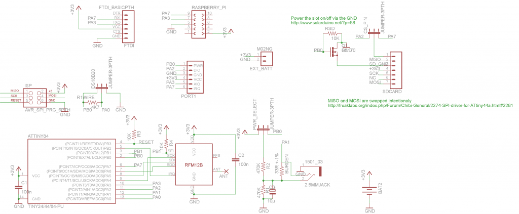
The TinySensor is a ATTiny84 based multi-purpose board. It is designed to primary serve as a low power, battery operated wireless remote sensor that will measure and transmit data to a remote base at regular intervals. For the purpose, there is a dedicated temperature sensor port (intended for DS18B20 one-wire temperature sensor bus) and a configurable voltage divider.
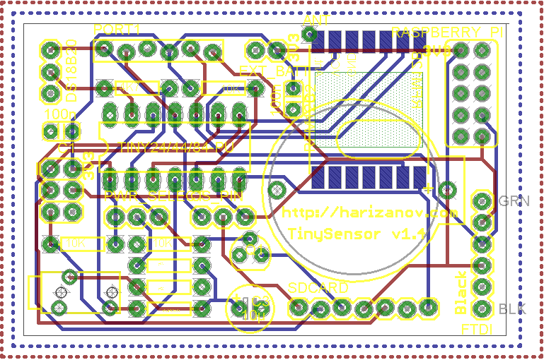
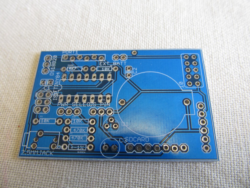
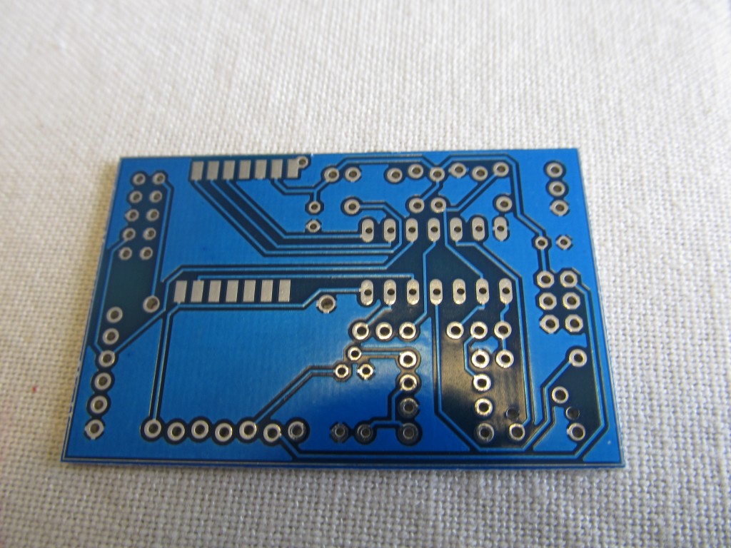
Schematic and board TinySensor v1.4_rev3
Numerous applications and hardware configurations are possible, some examples include
- Temperature sensing
- Air Humidity Sensing
- Light Intensity sensing
- Current sensing (for power monitoring)
- Soil Moisture sensing
- Water flow sensing
- Switch position sensing
..and many more, limited by your imagination only. See my projects tagged with Attiny84
The module has on-board RFM12B transceiver module, so it is able to communicate with other modules in the wireless network.
Additionally, there is a SD card pin connector, that allows storing measurement data on a SD card, in really remote locations that may be useful option.
There is a Jeelabs JeePort, so you can benefit from all JeePorr compatible sensors /libraries out there
A 3.3V FTDI connector can be used to power the board and serial bi-directional debugging (no programming yet)
A CR2032 battery slot can be used to power the board when the application permits ultra-low power mode and long intervals between transmissions of data.
A Raspberry Pi connector allows plugging the TinySensor directly on a Raspberry Pi and using UART to communicate between the two modules. A good example usage is the RFM12b to Raspberry Pi serial gateway project.
Building it
Building the TinySensor is pretty much trivial. Start with the lowest profile components and gradually add them in the order of height, this way the taller components won’t stand in the way.
I usually start with the 10K resistors that keep the ATtiny84 reset and RFM12B’s Slave Select lines pulled up. If you will not use the ISP for programming, these two resistors may be omitted.
If you intend to use the DS18B20 temperature sensor, you need to solder the 4K7 resistor that keeps the data line pulled up. I prefer to add headers instead of soldering the other resistors, so that I can change configurations on the run.
Next, solder in the two decoupling capacitors. These are ceramic and orientation doesn’t matter.
I then solder the RFM12B module on the bottom of the PCB. The orientation of the RFM may be a bit tricky to figure at first. The crystal needs to go on the inner side of the pcb. Apply a small amount of solder on one of the pins so that it affixes the whole module. Adjust if necessary so it is in the middle of the footprint. Once positioned, solder carefully all connections. I hold the soldering iron a bit longer when soldering the RFM12Bs so that solder falls in the bottom of the module as well. Make sure there is solder on the top of the pad as well, I have had issues where I didn’t have enough solder applied. The antenna needs to be 82mm for 868Mhz modules.
You can now solder a 14 pin socket (or the ATTiny84 directly, if you need low-profile, but the socket is recommended for most uses) and the ATTiny84. The silk screen shows the correct orientation of the socket and the chip.
Next is the 6-pin ISP connector, if you will use it to program the ATtiny.
This is the basic configuration to get you started
Programming it
Check this post on how to setup Arduino IDE for working with ATTiny84.
Using it
Check the code repository for TinySensor on github.
Using the TinySensor with a Raspberry Pi
Note: Prior to doing any further work, please backup Raspberry Pi’s SD card.
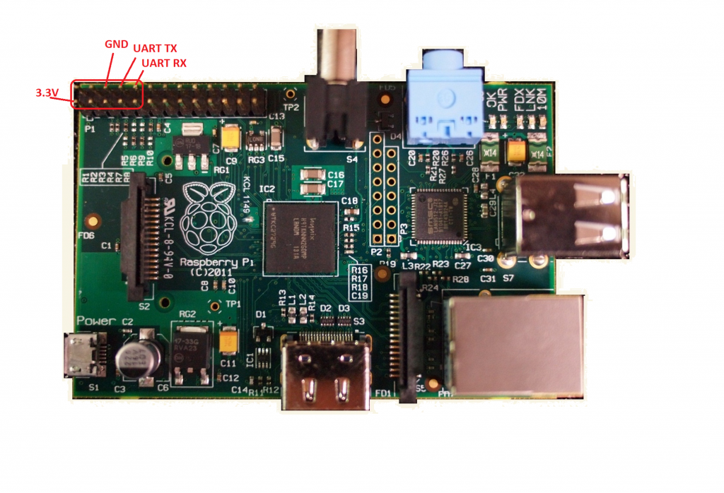
The TinySensor has a dedicated port sized 2×5 pins, that allows it to be plugged on a Raspberry Pi. It will get its power from the 3.3V line and will connect Pi’s UART TX and RX TinySensor’s PA3 and PA7 respectively.
When plugging the TinySensor on the Raspberry Pi, make sure of the following:
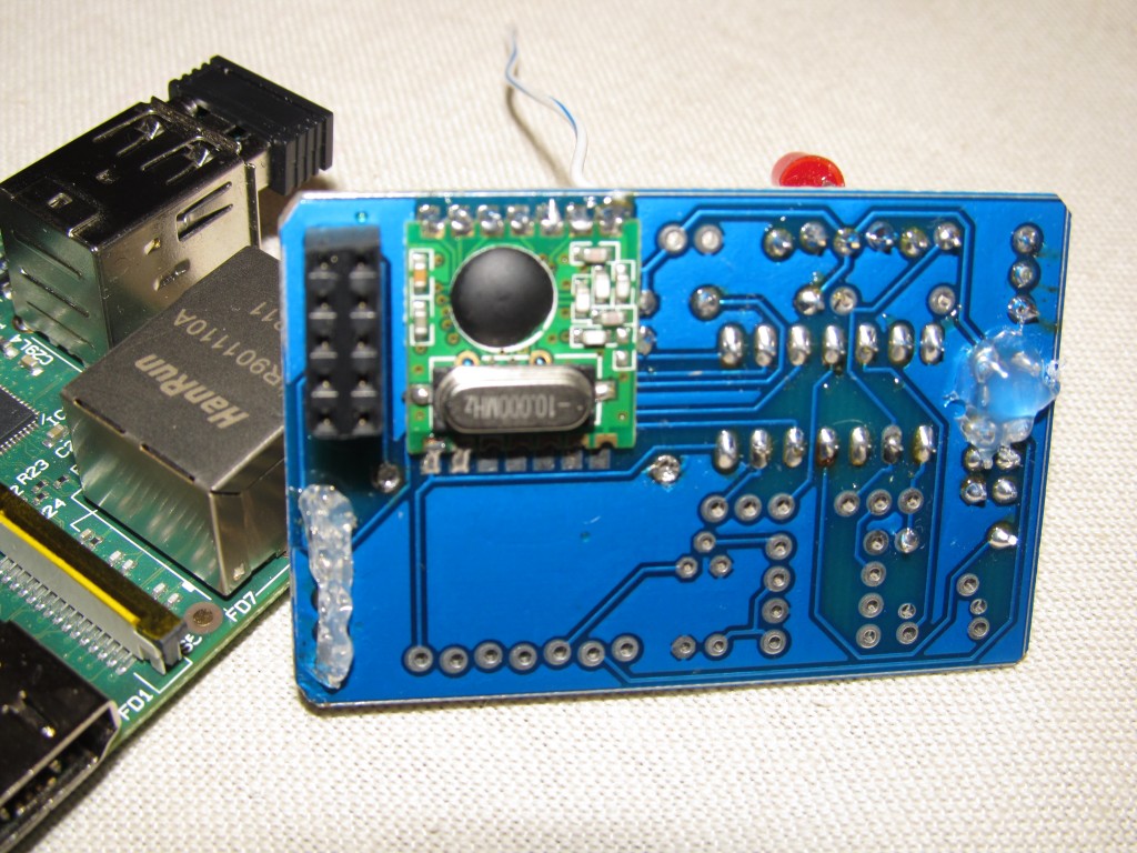
- The TinySensor board is held on the Pi by the 2×5 pin header only. If pressed, it may contact the Pi’s other components. I apply a small amount of hot glue silicon on two points, where potential contact between the TinySensor and the Raspberry Pi may occur, you can use isolation band as well. These points are the FTDI connector (if soldered, the connections are close to Pi’s GPIOs) and between the ISP connector and DS18B20 port, so that the board doesn’t touch the large capacitor on the Pi:
- The TinySensor should not be powered from another source.
- Don’t plug FTDI cable directly in the FTDI port as it provides 3.3V too. You may use FTDI for serial debugging by connecting it with jumper wires, you need only GNS, TX and RX lines. Leave the FTDI power unconnected
- If you have the CR2032 battery installed, please remove it. If you have other batteries installed at the external battery connector, make sure they are disconnected
- If you have ISP programmer connected, please make sure it does not power the TinySensor. There is a jumper on most ISP programmers that disconnects the power line
- Make sure Raspberry Pi’s UART is disconnected from the console and available for programs to use it
- First, make a backup of the cmdline.txt file
sudo cp /boot/cmdline.txt /boot/cmdline_backup.txt
-
- Next, edit it to remove references to Pi’s UART (ttyAMA0)
sudo nano /boot/cmdline.txt
-
- Originally it contains this
dwc_otg.lpm_enable=0 rpitestmode=1 console=ttyAMA0,115200 kgdboc=ttyAMA0,115200 console=tty1 root=/dev/mmcblk0p2 rootfstype=ext4 rootwait
-
- Edit it to look like this
dwc_otg.lpm_enable=0 rpitestmode=1 console=tty1 root=/dev/mmcblk0p2 rootfstype=ext4 rootwait
-
- Press Ctrl+O to save, then Ctrl+X to exit
- Next, type “sudo nano /etc/inittab” and comment (or remove) the line (towards the end of the file)
2:23:respawn:/sbin/getty -L ttyAMA0 115200 vt100
- Restart the Raspberry Pi by typing “sudo reboot” so changes take effect
- I use minicom to view the serial data
sudo apt-get install minicom
And to run it at 9600 baud (or change that to whaterver baud you used on TinySensor’s side:
minicom -b 9600 -o -D /dev/ttyAMA0
Tip: you may use “sudo minicom -s” to store these settings as permanent



very cool design, I am interested in if this design would benefit from the addition of a RTC? I’m considering building a data logger for placement in a harsh remote environment and logging in date / time of the reading is important
You can “plug” an RTC in the JeePort of the TinySensor
See it here: http://redtry.jeelabs.org/projects/hardware/wiki/RTC_Plug
Hi, Received and assembled my TinySensor 1.4 today thanks. Project is Raspberry Pi with rfm12b(as emoncms base). I’m using arduino to programme TinySensor and not sure how to connect together (ok with sw I think). Can I use use dedicated port (sized 2×5 pins) on tinysensor and a few wires. Can you please provide wiring diagram or guide. Many Thanks Peter
Hi Peter,
The 2×5 header is for connecting to the Pi only, you can’t program it from there. If you don’t own an ISP programmer, then I think our next best option is to follow Nathan’s instructions as provided here http://nathan.chantrell.net/20120225/an-attiny-based-wireless-temperature-sensor/
see the section “Using an Arduino as an ICSP programmer”. That will require that you take out the ATTiny84 chip (I hope you used the dip socket I also include), Nathan’s post has a pretty good close-up picture of the wiring as well, plus a description.
I guess you have set up your Arduino IDE to work with ATTinys as I described here: http://harizanov.com/2012/08/setting-up-arduino-ide-for-working-with-attinys/
If for some reason this turns out hard, I can send you pre-programmed ATTiny84 that you will only have to plug in. As you probably noticed, I now offer pre-built and pre-programmed rfm2pi board, because I was afraid of such situations :). Anyway, that takes away a part of the learning experience, so when you manage it, you will have a lot new knowledge.
You have my email address (the paypal address), you can contact me for further guidance there. In any case, let me know how it worked out.
Hi Martin,
Thanks for guide, | think I nearly there. I have uploaded to Attiny84 using arduino. I get the following:
Binary sketch size: 7,474 bytes (of a 8,192 byte maximum)
avrdude: please define PAGEL and BS2 signals in the configuration file for part ATtiny84
avrdude: please define PAGEL and BS2 signals in the configuration file for part ATtiny84
Com 7 displays @9600: yyy
Is there any way to test its working before putting back into TinySensor. Whats next step. I have raspberry pi ready to go (I think).
Thanks
Peter
Good,
Indeed you are making progress, the sketch size matches what I get.
As Nathan says in the post I referred, the ‘PAGEL and BS2’ message can be safely ignored, as long as it says “Done uploading” at the end.
How did you get the COM7 output? Did you use a FTDI cable for the purpose? Testing is easy, just hook the VCC, GND, TX and RX pins to FTDI and you shoud be able to see some output @ baud 9600. Note that if you have a 5V FTDI cable, you can do this only with the ATTiny chip removed from TinySensor as the 5V will destroy the RFM12b module (bit it is safe for the ATTiny)
I assume you have the ATTiny operate at 8Mhz, otherwise it will not work with the RFM12b
ATTiny84:
rxPin 7 //PA3

txPin 3 //PA7
FTDI cable:
BLACK – GND (hook to Tiny’s GND pin)
BROWN – CTS (don’t use)
RED – 5V (hook to Tiny’s VCC pin)
ORANGE – TX (hook to Tiny’s RX pin i.e. PA3 aka digital 7)
YELLOW – RX (hook to Tiny’s TX pin i.e. PA7 aka digital 3)
GREEN – RTS (do not use)
Anyway, make sure the terminal program runs at 9600 too. It is perfetly safe to return the chip to the TinySensor and test this on the Rasperry Pi with minicom terminal program
Hi, No luck over weekend. I had to reload fresh wheezy on raspberry pi as it hung and I now have some issues with wifi (wr703n on openwrt) on ethernet. Will try again next weekend. I’ll keep you posted on progress.
Thanks
Peter
Sorry to hear about it. Please keep me posted.
Hi, Do I need to configure TinySensor e.g. frequency 868Mhz, Network 212 and node ID 31 (tinysensor). If I do could you please provide a guide or example.
Thanks in advance. Peter
Type ‘h’ in the serial console to see the current configuration and help:
Available commands:
i – set node ID (standard node ids are 1..26)
b – set MHz band (4 = 433, 8 = 868, 9 = 915)
g – set network group (RFM12 only allows 212, 0 = any)
c – set collect mode (advanced, normally 0) a – send data packet to node , with ack s – send data packet to node , no ack
l – turn activity LED on DIG8 on or off
q – set quiet mode (1 = don’t report bad packets)
(or enter an uppercase ‘A’..’Z’ to set id)
…,
…,
Current configuration:
65 i1 g210 @ 868 MHz
so basically to set the node id you type this command:
25i
this will set the node ID to 25. Type ‘h’ to confirm it visually in the “Current configuration” line.
To set the band type the following:
8b
this will set the band to 868Mhz. Type ‘h’ to confirm it visually in the “Current configuration” line.
to set the group type:
210g
this will set the group to the default one 212. Type ‘h’ to confirm it visually in the “Current configuration” line.
That’s the most important set of commands.
What data are you going to pick up?
Hi, Thanks a mil. One more question please. What’s the serial console? – please excuse if a dump question. I using arduino uno as ISP to load RF12demo and minicom on raspberry pi. Cheers Peter