
[This project is obsoleted and not supported]
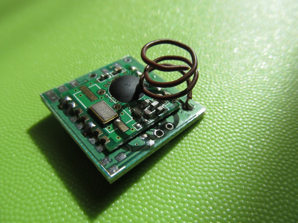
The ‘Funky’ Sensor is a miniature ATTiny84 based node with a RFM12b module for wireless communications. It was originally created by Tobias Floery, and inspired by Jeelab’s JeeNode Micro. I was quite impressed by the small size and usability of the device and asked Tobias for permission to copy and develop further a version of my own.
My revisions include
- Added voltage step-up circuit based on the LTC3525 boost regulator chip , the exact same as the one found on Jeelab’s AA power board.
- Removed the battery voltage sensing circuitry as it can be achieved using the bandgap method
- Added micro-USB plug, so that the node can be powered from there (only power function, no USB communication). The voltage regulator is retained, so alternatively the Funky can be powered from a source up to 7.5V
- I added provision for a 4.7K or 10K between pads 4 and 5 on the Funky, that will allow directly soldering DHT22 humidity+temperature or DS18B20 temperature sensors (or any other sensor that uses three pins and requires pull-up on the data line).
- The RFM12b clock out pin is connected to ATTiny’s CLKI pin, providing possibility for using RFM’s 10Mhz crystal for clocking. This required changing the LED pin.
The board measures 23 x 23.4 mm in size. I use the “flat crystal” version of the RFM12b module to keep it low-profile and to allow the optional CR2032 battery holder to be soldered on either side.
The latest Eagle design files are available here.


Building it
Because of its miniature size, I only offer pre-built Funky sensors in the store.
Programming the Funky
You need to set-up the Arduino IDE for use with ATTiny processors. I have shared my experience in this post. My already configured Arduino IDE 1.0.1 for Windows is available for download here.
You need a six pin ISP programmer to program the Funky. I own a clone of the USBTiny programmer, these are widely available on ebay and cost less than 10 dollars delivered.
Note: The Funky is a 3.3V device, and the RFM12b module cannot withstand more than 3.6V. When programming the Funky, make sure you don’t supply 5V thru the ISP programmer, or the RFM12b module will most likely be burned. The USBTiny programmer has a jumper on it that when removed, does not provide power to the ISP connector. You still have to provide 3.3V from other source so that the Funky can be programmed.
You need 6 pin ISP connector to program the Funky. The PCB is 1.60mm thick, while a 2×3 pin header has 2mm spacing. It requires a small bending to make better contact, use pliers to apply minimal pressure to the pins so they make better contact:


Prior to uploading a sketch, make sure you have set the correct fuses. I recommend running the Funky on the Internal Oscillator at 8 Mhz, because 1Mhz is not enough for sending/receiving RFM12B packets. Setting the fuses is done by selecting the appropriate desired option and then pressing “burn bootloader”. This doesn’t really burn a bootloader, only sets the correct fuses for this type of board. You only need to to this once, fuse settings are then “remembered”; Since I ship the Funkys already pre-programmed with a test sketch, I have already set the fuses to 8Mhz BOD disabled for you.

You can run the Funky on RFM12b’s crystal @ 10Mhz as described here, but only do this if you absolutely know what you are doing because you may end up with unresponsive Funky.
I ship the Funky Sensors with the “Internal Temperature sensor” sketch uploaded, it allows me to test the MCU and RFM module easily.
Example usage
Examples on github
Pads on the Funky:
Pingback: DIY Internet of Things Fire Alarm | Martin's corner on the web
Pingback: The body interactor BI01 – small is beautiful | body interaction