
It has been a while since my last post, I have a new job and little time left for hobby stuff 🙂 Anyway, I have put together the PCB for the Yet Another Power Monitor (YAPM) project and was able to do some preliminary tests over the weekend.
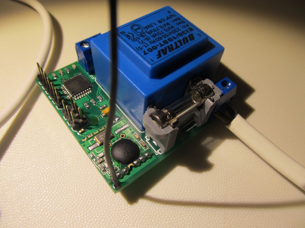
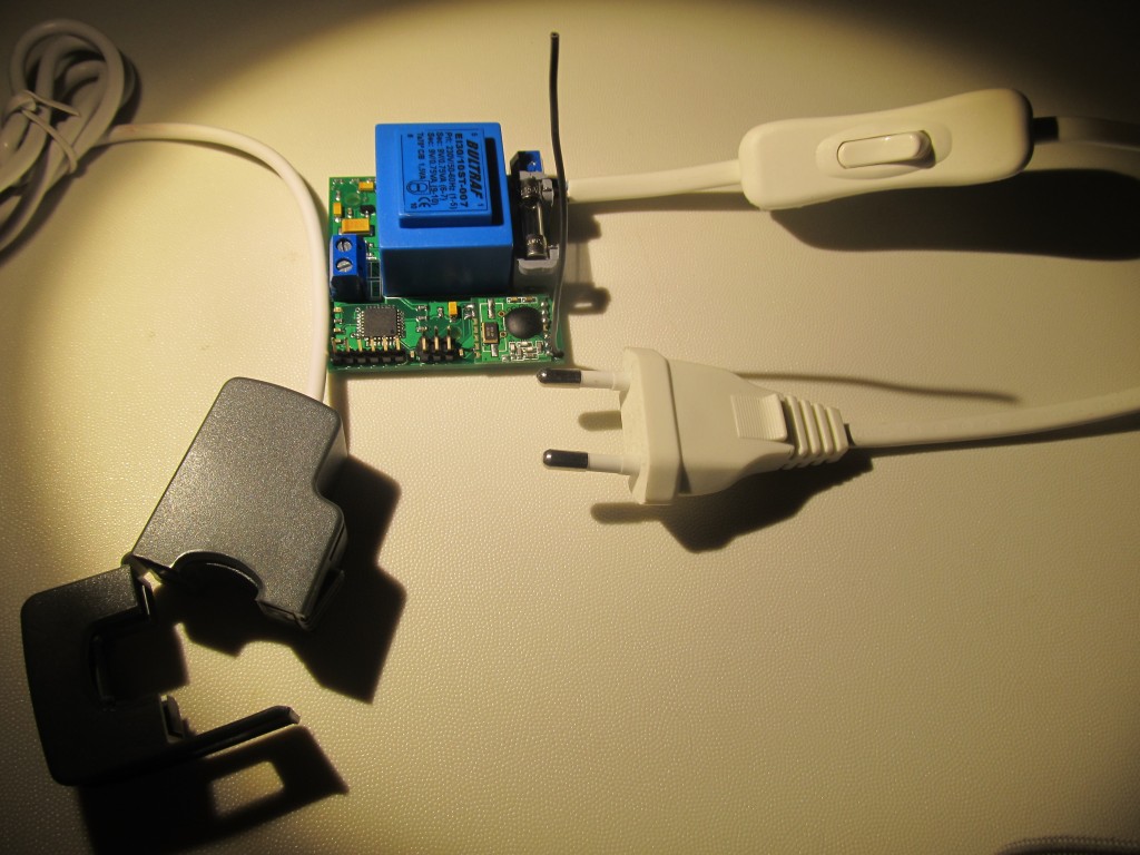
To re-cap: the YAPM is a low cost Arduino compatible power monitor that measures power (voltage and current) and transmits the readings to an Internet Gateway and/or one of my OLED status monitors. The goal was to make a single power supply unit, I used a transformer with two secondary windings – one for powering the thing and the other to measure the voltage. The total build cost for a fully functional unit, including the clap-on current sensor, is less than 30 EUR. The YAPM is based on the openenergymonitor.org project and compatible with emonTX code, except that it is single phase and doesn’t have temperature sensor/pulse sensor ports. I left those functions for the Funky to handle. The YAPM will typically be placed in or near the house’s fuse box, the PCB size is 5x5cm which makes it ideal to fit in a DIN rail box too. Here is how it looks:
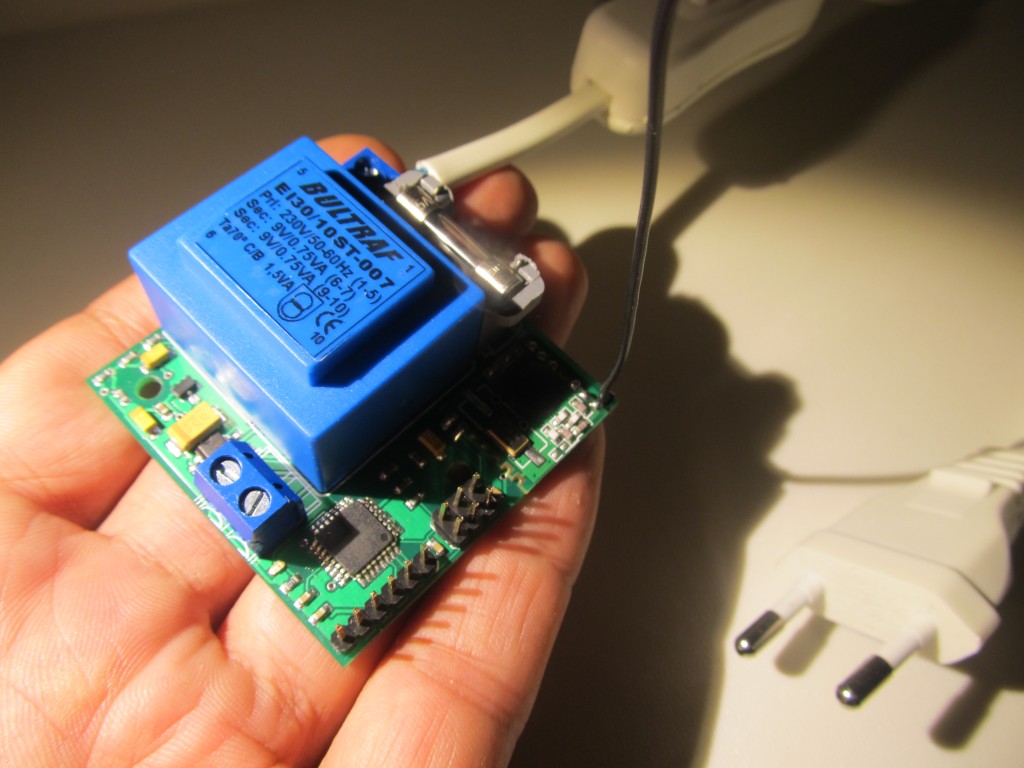
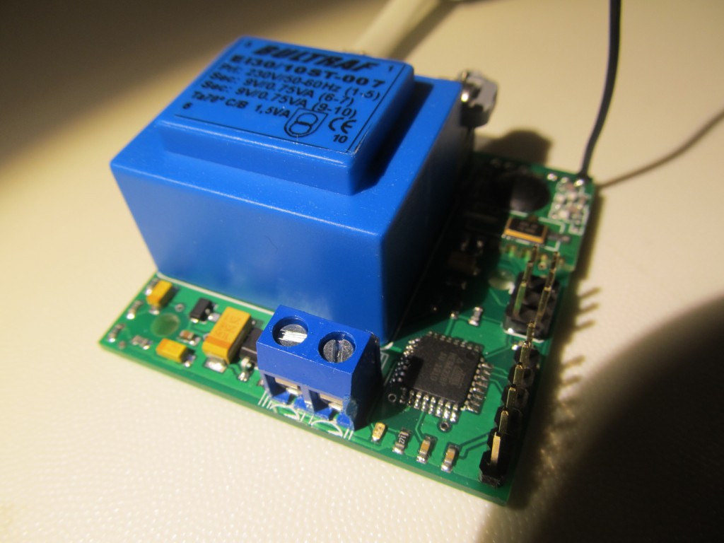
Since the YAPM connects live to the 240V line, it is quite dangerous to handle and can provide you with a quick, yet painful transition to the other side if you touch the live connections while it is powered on. I haven’t had the chance to find a suitable box yet, but it must be enclosed for safety reasons.
I tested it briefly and it works as expected. I will build few more units for close family members, but other than that the YAPM will probably not make it out in the wild because of the reasons outlined in the previous paragraph.
Love the name Martin! Looks like a nice little board. Obviously would have safety concerns if left un-cased but these issues are not impossible to overcome with good enclosure and proper separation. Your choice of what looks like titanium capacitors is interesting. What was the design design behind these? I would be interested to have a look at the Eagle schematic and brd files. Are these available anywhere?
Hi Glyn, you give names like that when you run out of ideas for appropriate project names 🙂 You probably sensed the slight sarcasm that went with the name. Yes, I’m yet to find a suitable case, it shouldn’t be a problem. The tantalum caps are there for few reasons, first they are small, then they have unlimited life span unlike electrolytic ones, and not least they can work from -55 to +125 degrees C.. Probably there are disadvantages too, but for this particular project, I thought they are a good fit. I haven’t set a Github repo for the project yet, let me email these to you as a starter.
price ? i need one with ethernet nor radio module. is this possible ?
It’s not for sale, due to lack of free time on my end. Adding Ethernet is relatively easy, but again…time issue 🙂
Perhaps you could redesign to accept a 12v AC wall wart? If you have no time to develop perhaps you could release the files? Keep up the good work