Dave Berkeley’s recent home power monitoring blog post got me thinking:
- How much does a DIY power monitoring system cost
- How accurate it is
I had a friend ask me how much my current power monitoring system costs. I really didn’t had that calculation, so it was interesting to check myself too, here is my calculation:
Transmission part:
- Arduino UNO at the breaker box: Cost €20
- Sensing Shield ontop the Arduino at the breaker box: Cost: €15.50
- RFM12B module for the Sensing shield: Cost: €7
- Current Transformer: Cost: €12
- Voltage sensor (AC-AC transformer): Cost: €16 (whoa!!!?)
- Power supply: Cost €5
- Arduino enclosure: Cost: €10
Total: €85.50
Receiving part:
- NanodeRF: Cost €35
- Power supply for the NanodeRF: €5
Total: €40
Total transmission and receiving components: €125.50
I will assume the hosting of the monitoring software is free, as I use the same server I host this blog, but that’s a cost not to be neglected over the years.
That can’t be good. Way too expensive, isn’t it.
Regarding the accuracy of the system, it is probably not so important for hobby project, still Dave explains the inaccuracies caused due to the usage of transformers to monitor voltage.
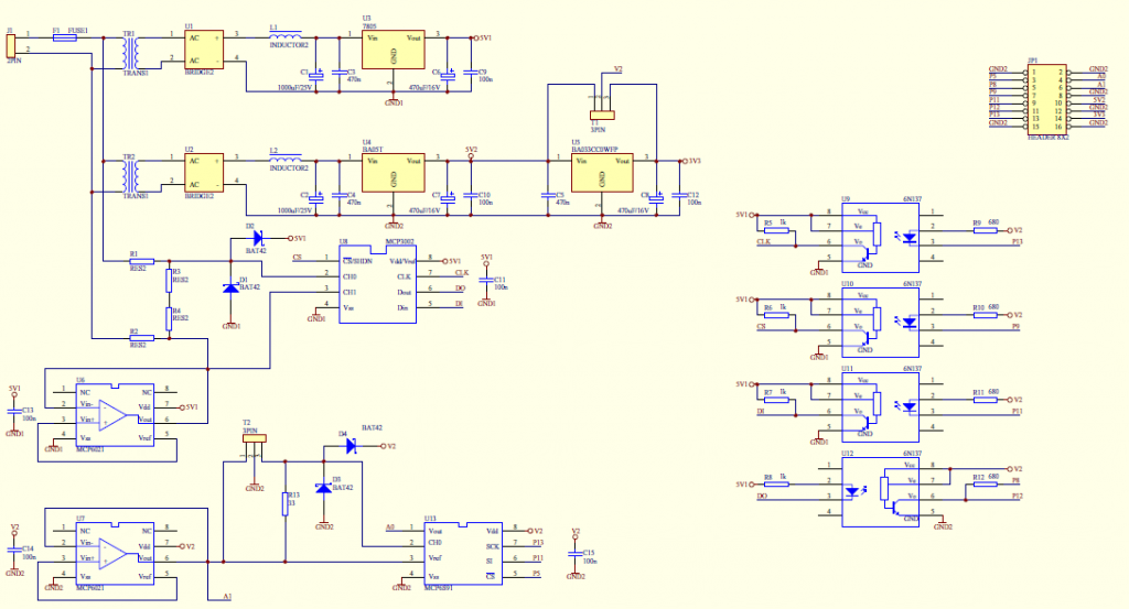
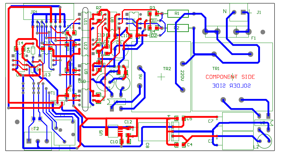
With these two arguments, I thought I want to experiment with creating a dedicated device, based on Dave’s work. The idea is to provide ADC measurements over isolated SPI and isolated power supply for whatever module needs to be attached to do the measuring (JeeNode or Arduino or NanodeRF and so forth). Combining most of the modules in one device will help cut down the cost.
This particular project involves high voltage, so I wanted (just as Dave) to have all safe and isolated. I have involved a friend (thanks Angel) to help me with the schematics and board layout.
The device will be named “e-meter”. Here is the current schematic and layout:
The layout is done in Protel, here are the above as PDF: Emeter sch ; Emeter pcb
The device will be fitted in a box with DIN rail. We will be ordering prototyping version of the PCB to experiment.
Comments are welcome


Hmmm,
you write that the AC-AC transformer (voltage sensor) costs €16, then you use two transformers for powering this node. Makes no real sense (although I understand your calculation!). And the transformer is not necessarily the ‘weak’ link in measuring accuracy (a 400V type can be very accurate when used at 230/240V AC).
Then you go only half way with measuring at mains potential. Why do you still use a CT (I think this is what T2 is used for ?): Why not use a shunt instead, this is much cheaper (<€1 compared to €10).
And then you could also use a dedicated IC for mains measurement, like the ADE7753. These are specially made for this pupose and include all the necessary building blocks 'onboard', like measuring, calculation, calibration (would relief the ATmega from all this). And they also have an SPI interface and are not expensive (<€3-4).
Just some thoughts, I do not say that your circuit is a bad ….
BR, Jörg.
PS: the basic question is if the whole thing shall be (or has to be) non-intrusive or not.
All good questions,
The transformer I use in my current setup is this one: http://shop.openenergymonitor.com/ac-ac-adapter-euro-plug/
while the ones on the PCB above cost 1.7 and 2.3 Euro respectively.
There are many options for on-chip solutions, Dave mentions quote
“I’ve also come across a new chip, the SiliconLabs Si890x Isolated AC Mains Monitor, which has a 3 input analog MUX, a PGA, 10-bit ADC and opto-isolated SPI interface all on a single device. This makes a very simple low cost system that would be better than my design. It would work with either a current shunt or CT interface.”
So this all is just ideas floating. I will be researching further for the best option for low-cost integrated device..
If we are voting I vote SiliconLabs Si890x but keep in mind it is a 25 Amp MAX measurer. To me good because I plan to measure at various places.
The 25A is a setback indeed. I think this chip was intended tor power plugs monitoring, I wanted something for the entire house. I have 60A max fuse, so that will not work 🙁
Instead of using a device like the SI890x (which is not much more than an isolated ADC), you could use a complete microcontroller (e.g. MSP430G) on the primary side with more functionality at a lower price.
The 25A is a limitation of the development board, not of the SI890X (this is just a 10 bit ADC which will give a value between 0-1023). The max current depends on the shunt or CT used.
Pingback: E-meter PCB ready | Martin's corner on the web