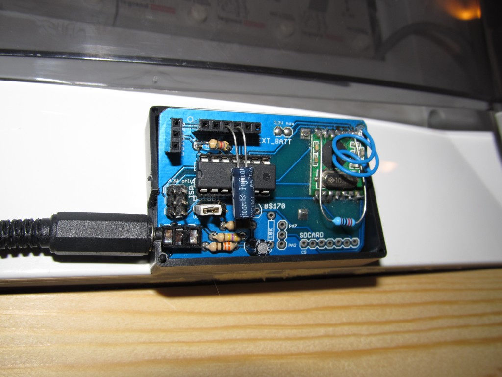
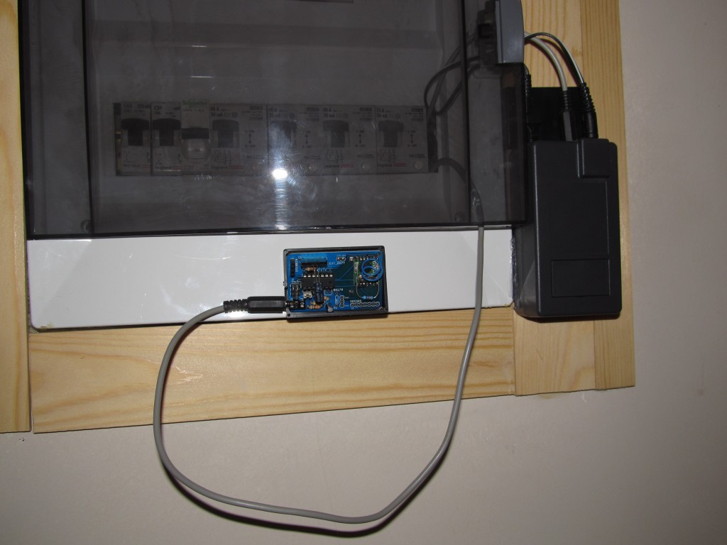
I am experimenting these days with one of the old versions of the TinySensors trying to see how long it can go with some heavy duty tasks, powered only by a single CR2032 battery. I wrote a small sketch to measure current using the on-board voltage divider, calculate apparent power based on assumption of fixed 220 voltage and send that to emoncms. I used serial output to calibrate the sketch with a 800W toaster 🙂 as pure resistive load. I had to use some strange calibration to get accurate readings, I have no idea why neither I investigated further. I installed the sensor near my breaker box, next to my existing Sensing Shield based monitoring system.
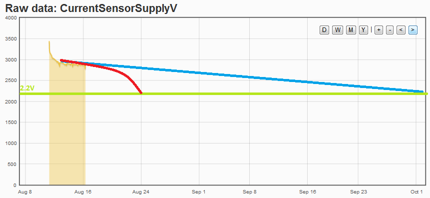
It sends every 10 seconds, then sleeps. I have used all the power-saving techniques so that it runs as long as possible. Honestly, I didn’t expect it to run longer than a day or two, but here it is running already five days.. I am pretty surprised, as this means it managed to send 6 times a minute* 60 minutes in hour * 24 hours in a day * 5 days so far = 43200 transmissions so far .. WOW, all that with just the CR2032! It is still sending, here is a graph of the battery level discharge:
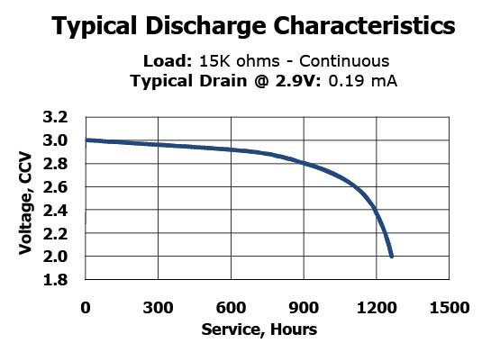
The sensor was powered on Aug 11th at 10:45am with a fresh CR2032. You can see the voltage drops suddenly, then stabilizes. Green line is the 2.2V level, where the RFM12B is supposed to stop working. The blue line is the linear virtual continuation, if CR2032 voltage drop was constant. I first thought it would last till October at this discharge rate, but this is too good to be true. I googled and found that CR2032 battery discharge rate isn’t linear, more something like this:
So the red line in my first graph is somewhat more realistic representation on what to expect. In any case, this is quite an achievement for 220mAh battery, imagine powering this thing from two AA batteries totaling 2200mAh..
I’ll post final results once it stops sending.


We are just discussing this somewhere else too, but I think that the ADMUX settings in readVcc() are wrong for an ATtiny48. It should be:
ADMUX = (1<<REFS0)|(1<<MUX3)|(1<<MUX2)|(1<<MUX1);
This reads the 1.1V and uses VCC as reference (as stated in the text).
BR, Jörg.
Thanks,
but I am not sure this is correct. Check against the Attiny84 datasheet, 16.13.1 “ADMUX – ADC Multiplexer Selection Register”
With the initialization you suggest, you would be reading ADC7 (PA7) against the internal 1.1V reference.
Can you post link to the discussion you mention?
I am getting pretty reasonable readings too.
hey, I just realized you are saying attiny48 while I use attiny84 … these are completely different, so your code may be right for your processor..argh 🙂
Ups, I am really sorry for that, Martin. I had been working with the ATtiny48 already some time ago and I knew that your code would not work for that one. And then you wrote that you had to use strange calibration value…….this must have mislead my eyes and/or brain.
Apologies again, and, this is a great project, forgot to mention this in my first comment!
Pingback: 64 800 transmissions | Martin's corner on the web