I have been working to upgrade the TinySensor v1.3 to a new version these days, that addresses the issues I had identified so far. I am keeping it in through-hole components for easy soldering and also so that one can easily use different configurations by soldering/de-soldering certain components. PCB size is unchanged (38x56mm), Here are the highlights, feel free to comment as I am probably going to give myself few days for re-thinking before putting it in production, your feedback is important.
Below is the external battery connector, I use that to power the sensor from two AA batteries when more power is necessary. When using the CR2032 battery, I sometimes solder a header there to connect a 10uF electrolytic capacitor to ensure less sudden voltage drops when powering multiple sensors at the same time.
I changed the CR2032 battery holder with a different one, this takes up less space and can be soldered either on the top or the bottom of the PCB, depending on the concrete build needs: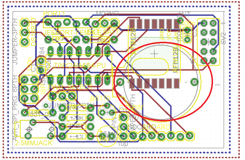
I now have the two pull-up 10K resistors on ATtiny’s RESET and RFM12b’s ChipSelect lines that were missing in the old version and required fixing: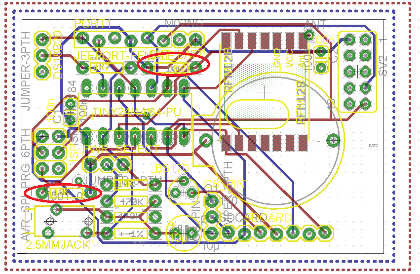
I added two decoupling capacitors, the old version works just fine without them, but it is good practice and will be necessary when hooking up the TinySenor to a Raspberry Pi for example: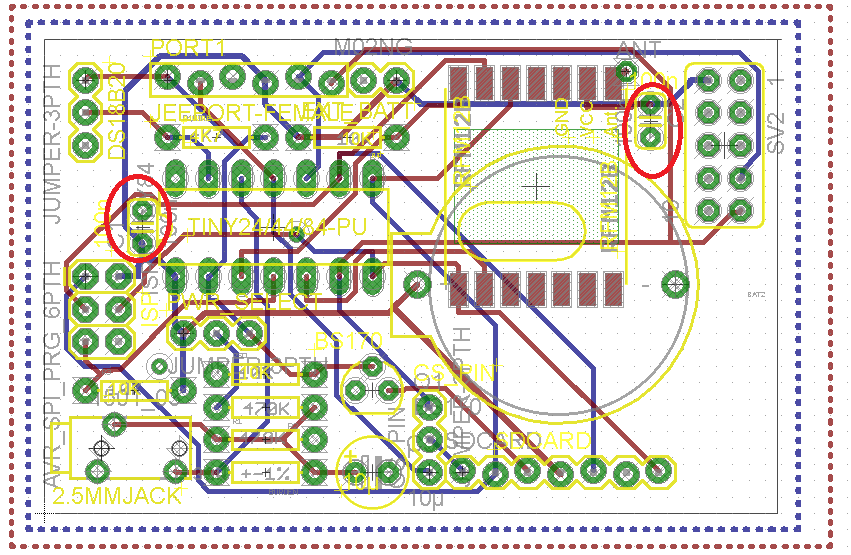
I added a small connector that allows me to plug the TinySensor directly on a Raspberry Pi, see my other home etched PCB to get idea how. In that scenario, the TinySensor will get power from the Pi. The right part of the PCB is intentionally left clear of components so that they don’t interfere with the connector that is larger, but we only need few of the pins for serial communications: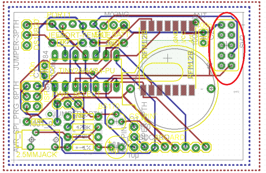
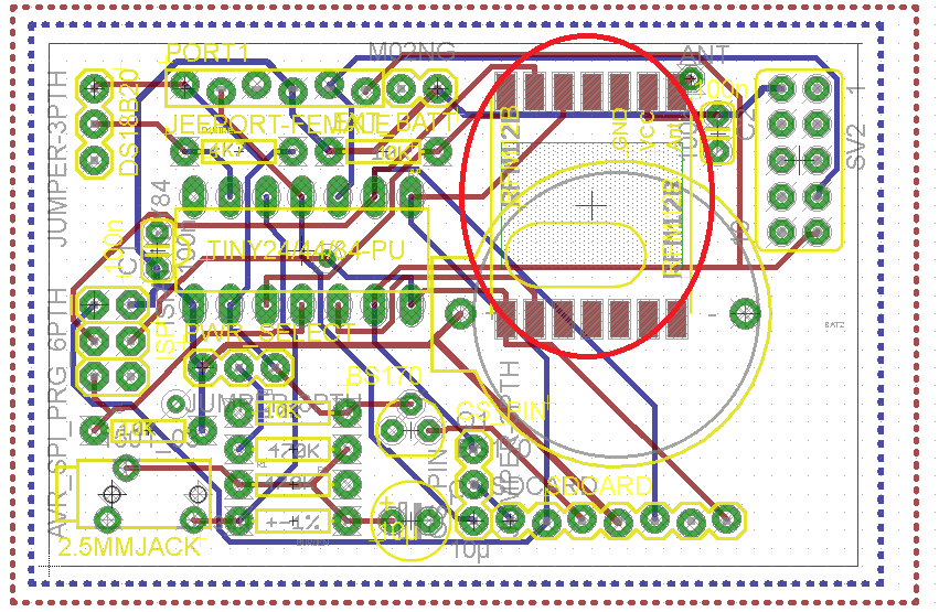
Nothing material changed with the RFM12b:
I re-arranged a bit the resistors of the voltage divider so that you can solder headers on top. This way you can simply insert the resistors without having to solder, great for prototyping work. Note the voltage divider power selector, this is done with a jumper: you can power it either constantly or via a digital pin (PB0):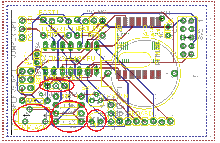
No changes in the SD card circuitry, it also has chip select pin jumper: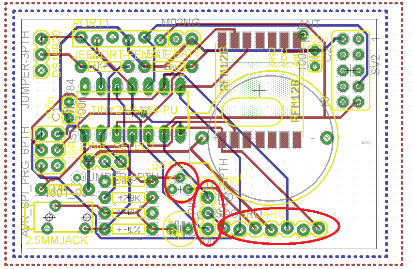
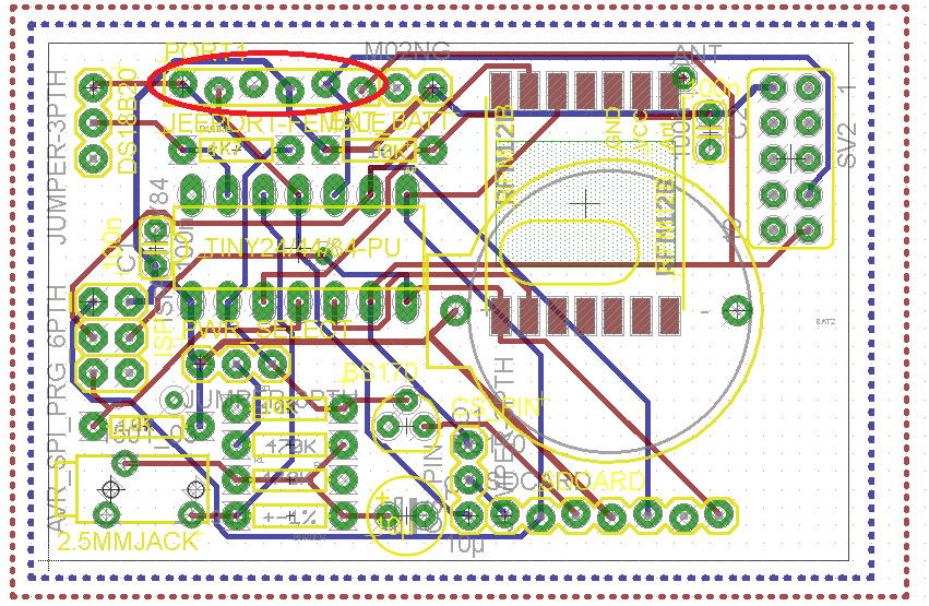
There is a JeePort on the top of the PCB, compatible with Jeelabs ports library. This means you can plug lots of sensors there, including I2C:
No changes in the temperature sensor port. I keep it flat so that header can be soldered, thus making it easy to just insert/remove a DS18b20 or a TMP36, DHT11 or any 3-pin sensor. For using one wire sensors, the 4.7K resistor must be soldered. The port is powerer by setting PB0 to high, this way keeping energy consumption at low:
So basically this is it, again, please do comment with suggestions 🙂
Eagle schematic and board files are available here: TinySensor v1.4


Sounds great Martin! Good Idea also including a jeeport.
Pingback: TinySensor 1.4 PCB is ready | Martin's corner on the web