
When you run a project on battery, you are always thinking on how to conserve power so that you run longer. In the case of wireless remote nodes you do that by sleeping a lot and only waking up briefly to do some useful work (I know people that do the same). That requires a set of techniques – both hardware and software.
The hardware must be designed in such ways that low sleep power consumption is possible. Those of you following my blog may recall my woes with the MCP1703 LDO on the early Funky v2 prototypes, those would leak current when the Funky is powered from a battery i.e. the VOUT side is powered and the VIN not. I then found out that a MCP1700 performs better, but not ideal. I managed to get sleep currents at about 0.06mA/3V but had to keep battery power at less than 3.1V or the side effect happened again. For that reason I used the 3V version of the LTC3525 boost regulator on Funky v2. That still bothered me and I was looking for a LDO replacement ever since. Couple days ago I found the Torex XC6206 LDO series, those have in-built diode to prevent the parasitic currents I was experiencing: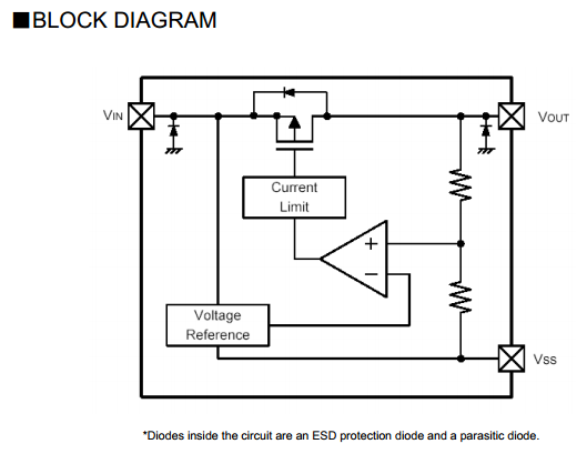
I purchased few to try out and they work really well in eliminating that minimal but pesky parasitic leak – saving me extra 0.02mA and resolving the boost regulator issues. I can now again use the 3.3V versions of the LTC3525, although the 3.0V is more efficient. The quiescent draw is also better than the MCP1700 – only 1uA. I will use these in Funky v2 from now on.
Another hardware consideration that the Funky v2 has is the option to power up/down the on-board RFM12B transciever using a MOSFET. This allows for better power management and powering the RFM12B module from the software. The RFM12B has pretty high start-up power consumption, so you may power and put it to sleep only when you have sufficient power.
The clock source and frequency that you run at also has great impact on power usage. You get lower power consumption when running on the internal oscillator and lower frequency. Luckily, the ATMega32U4 that I use in Funky v2 has software control over both meaning you can switch between the internal RC oscillator and external crystal plus you can control the prescaler to run at different frequency. This gives you the option to decide which cock source and frequency to use depending on the particular application. I have an example on how to switch between clock sources and set the prescaler here. Changing the frequency at which the MCU runs is also necessary when running on low voltages, the Funky v2 has a 8Mhz crystal on-board because a 16Mhz crystal will require at least 4.5V. Running on 8Mhz requires at least 2.7V, but I have tested it to work reliably at a little less too.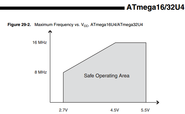
Running on lower voltages will require that you lower the frequency. The RFM12B transceiver can communicate with the MCU down to 4Mhz, so running slower than that will prevent you from using it. Of course you can speed up/slow down as necessary.
Fuses are yet another possibility to save power. The fuses determine how the chip will act, whether it has a bootloader, what speed and voltage it likes to run at, etc. Note that despite being called ‘fuses’ they are re-settable and don’t have anything to do with protection from overpowering (like the fuses in a home). The Brown-out-detection (BOD) can be turned to save another 0.02mA, here are the fuse settings to do this for the Funky v2:
avrdude -v -v -patmega32u4 -cusbtiny -e -Ulock:w:0x3F:m -Uefuse:w:0xcf:m -Uhfuse:w:0xd8:m -Ulfuse:w:0xff:m
avrdude -v -v -patmega32u4 -cusbtiny -Uflash:w:Caterina-lilypadusb.hex:i -Ulock:w:0x2F:m
Choosing the right power source for the project is important. Probably the hardest to deal with are the coin cell batteries – CR2032: these offer really small capacity of only 210mAh. I have also noticed that these are really sensitive to temperature and will drop their voltage notably when brought to low temperature. Picking the right battery depends on what you use your node for. A good tool for battery budgeting is this one, as you can see it all boils down to these parameters:
- What is the sleep current of the node
- How often does it wake
- What is the current consumption during wake state
- How long is it awake
Knowing these, one can estimate the expected battery life and plan accordingly. To get an idea of what is happening when running the DS18B20 sketch, I hooked a Funky to my oscilloscope. I also have Digital 13 go HIGH when the node is woken from sleep and LOW just before it goes down, so I can have a visual of the time when it is doing its job. This is the blue trace of the screenshot below, the yellow trace shows the current consumption times 10 in mA.
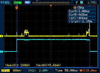
The sketch measures battery level, blinks the LED briefly, initiates DS18B20 conversion and waits in sleep mode (375ms for 11bit resolution) for it to finish. Once it is finished, it would transmit that value. So the whole thing happens for 466ms and average power consumption is 0.566mA (peaking to 26mA during transmission). The sleep current of the node is about 0.02mA (see screenshot at the end of this post). Lets assume 12 transmissions per hour i.e. one every 5 minutes. Punching in the numbers for a CR2032 coin cell battery gives me this:
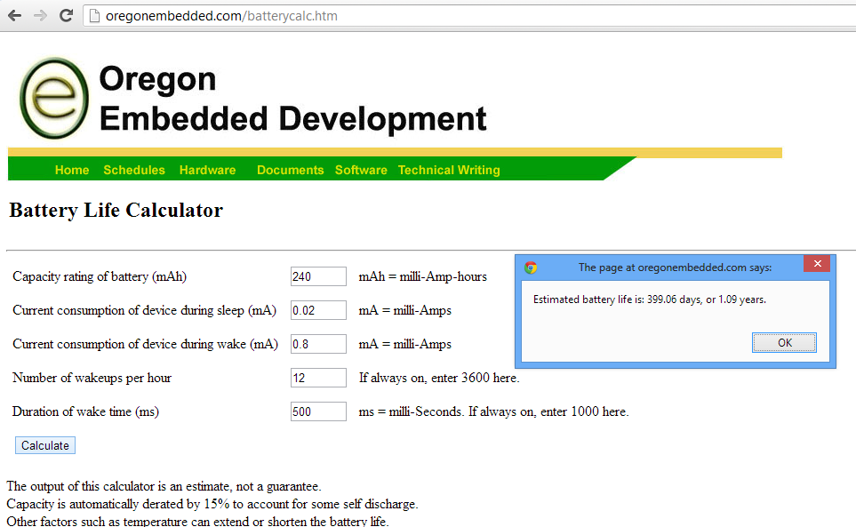
1.09 years.. sounds good, I have doubts that this is realistic though 🙂
Most of the power consumption comes from the RFM12B transciever. It can eat up 24mA during active transmission. As I have experimented earlier, the modules’s transmission power can be lowered at the cost of range, so nodes that are closely located to the gateway may save power. It is a subject to experiment to find the lowest power settings that is sufficient to get the payload transported reliably to the gateway.
Speaking of payload, it too has to be designed smartly. Sending float values will use up 4 bytes, the larger the payload size the longer it takes to transmit it. I typically use integers to send floats by multiplying the value by 100, so a temperature reading of 36.74 will become integer value 3674 and fit two bytes. The receiving side has the task to reverse this, I do that by setting a processing rule in emoncms.
Another consideration would be how frequently to take/send telemetry readings. I see many users using unnecessarily frequent readouts, in my experience taking temperature readings for a room node more frequently than once every 5 minutes is an overkill. Use the largest interval you can without compromising data quality.
The software must power down all unused peripherals to save power, that provides great savings. I include that in every sketch that requires low-power mode, see an example here, function powersave();
I use the digital pins to power up/down small sensors attached to Funky’s pins since some of them still consume notable amounts of power even in idle mode.
The code should be checked for effectiveness, for example I have optimized the DS18B20 digital temperature sensor code by a factor.
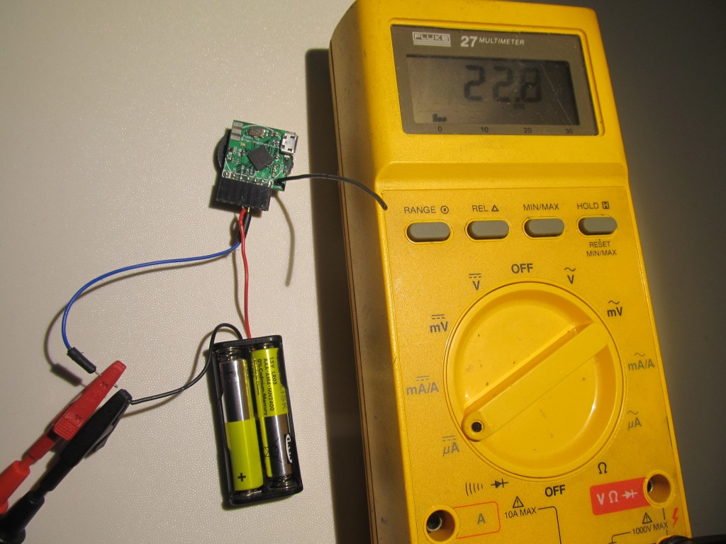
So putting these trick to work I get sleep currents of 22.8μA when running off 2 AAA batteries (3V).
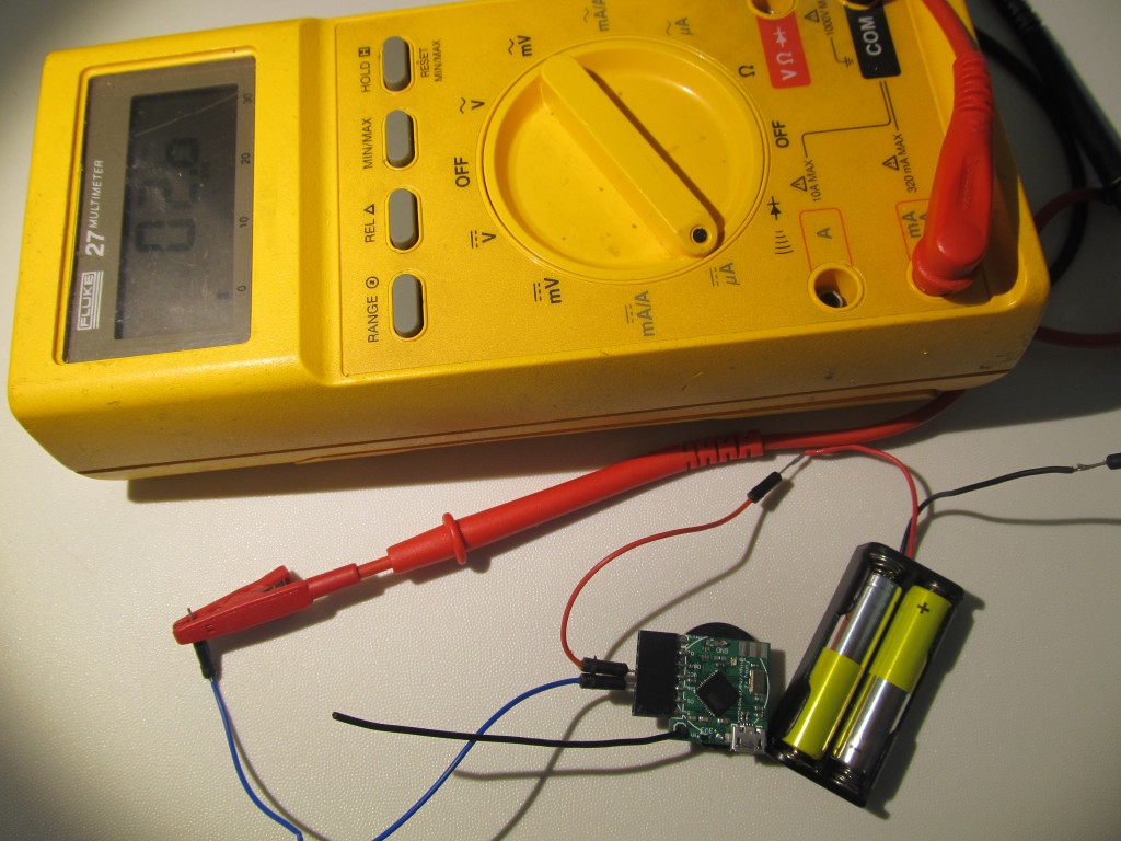
EDIT: Even 22uA seems high, so I tried to remove the LDO whatsoever.. I then got 2.6uA in power down mode.. amazing improvement. I guess I need to find a way to bypass the LDO when running on battery:
Do you use the wdt timer inside ATmega? This one burns a lot of power compared to the times inside the RFM12b module. I’m successfully running a few battery-powered ATmega328P projects at about 2µA in sleep mode. Actually it’s more a “coma” than “sleep” as it requires an external interrupt from the RFM12 module to wake up again.
First initialize RFM12B module and register a wake-up interrupt in, let’s say 300 seconds. Then completely shut down the ATmega with no timers running. The wake-up interrupt will wake up the ATmega after about 300s (+- 10%).
It’s not too easy to make it work and it may not even be possible depending on the RFM12 driver you use. But it may be worth a try.
I have been meaning to experiment with RFM12b’s wake up timer for some time, can you hare the code for setting the timer?
I am not sure it will make a huge difference though, I have tried both sleeping and power down modes, difference isn’t that great. Maybe the ATMEga32u4 isn’t as efficient in low power as the Atmega328, or I am omitting something in the code..
I have integrated it into jcw’s code for the RFM12b. That’s the code I’m using on my nodes right now.
https://github.com/jcw/jeelib/tree/rf12mods
Here some old infos about the changes:
http://forum.jeelabs.net/node/15592679.html?page=1
(sorry for linking to my stuff on the other forum, but I think it may be helpful)
I removed the LDO whatsoever with the same sketch already programmed.. I got 2.6uA in power down..wow
I guess that I need to isolate the LDO when running on battery power
It may really be worth a try… I entered the numbers in the online calculator you linked. According to this, the battery would last for almost 7 years 😉
Disabling brown-out detection must be done with care. When the batteries begin to fail and the voltage falls below the minimum required for correct operation the microcontroller is likely to run any random instruction. One of those instructions might be to wipe a page of flash memory. I found that out the hard way, replacing the batteries failed to restart the system. Analysis indicated several pages of flash memory had been set entirely to 0xFF, including the very first page.
I no longer use the fuses to disable brown-out detection but instead use the AVR library function sleep_bod_disable() to disable it during sleep mode. Not all Atmel microcontrollers support it – you’ll need a picopower variant (that’s the difference between the ATmega1284 and the ATmega1284P). I’ve not tried it but I think disabling the brown-out detection by setting a fuse should be safe as long as you also set the lock bits to prevent further programming of the flash memory. More information about my experience can be found on my blog post http://blog.stevemarple.co.uk/2013/02/the-importance-of-brown-out-detection.html
Hi Steve,
Unfortunately the ATMega32U4 that I use doesn’t have software control over the BOD, it is only set in the fuses. I haven’t heard of a ‘pico’ version, maybe it doesn’t exist for the ATMega32U4.
I am surprised that in your case you ran in trouble as I’d expect the boost regulator to ‘cut’ power rapidly after it fails du to low battery levels, the LCT3525 that I use will work down to 0.8V and then eventually just stop; I understand the MCU needs at least 1.7V for the transistors to work, so this ow voltage will mean it doesn’t work at all.
So I guess it is a fine balance between squeezing out few uA (20uA for BOD enabled) and expected battery life.
Martin,
I am designing some board like yours (but with ATMEGA 328) with FDTI conector (but no ftdi chip on the board) and I am facing the same problem. On 1st revision I put a little switch to choose between FTDI power or battery power.
The new revision is now using LTC3525 (I am also trying other from Maxim and TI). My question is why do you need additional LDO regulator and not using the LTC3525, because if VIN of ltc > Vout (in your case 3.3V) this one is working as bypass and not using the DC/DC converter ? It is even best than that because I’am also using my board with lipo battery (from 4.2V to 2.8V) and the LTC does the job with constant ouput of 3.3V. I did not checked the comsumption, but I will to be sure.
Charles
The LTC3525 is quite expensive, so I keep it as a option. The LDO is necessary for the USB connectivity to work as USB provides 5V that I ned to scale down to 3.3V, I have to think of ways to bypass it when running on battery. A switch would work, but space is so limited..
Martin,
Reading back your article, it is so interesting, thanks for sharing.
I understand the need of the LDO when you power the board with USB (5V) but I tought the LTC3525 was capable also to generate regular output 3V3 (or 3V depends on version) even if input was > 3V3, so my question is : have you tested putting the USB power directly to the input of the LTC, just curious. If not I will do soon, the MAX1724 for example don’t do that, if Vin > Vout+0.6, then Vout = Vin-0.6, that is fine for lipo because even with 4.2V board will be maxed at 3.6V. But if you put 5V on input (for example during programming with FTDI) wou will fry 3V3 sensors (not Atmel)
Also as your tests for current comsuption is without LTC, do you have any idea what is the consuption in sleep mode when powering the board with 1 AA or AAA with LTC enabled ? If not I will do some tests, I’m currently working on things like that too.
I’m searching to find a DC/DC boost with bypass to increase cell or battery life and activate the boost only when needed, the idea could be that the Atmel check voltage, then if become below critical threesold, engage the boos mode to put AAA or AA in 2nd life.
Once again, thanks for sharing your excellent job.
The LTC3525 + supporting components are relatively expensive, plus add 7.. 30 µA of current in idle mode (depending on input voltage). You could shut it down, using the SHDN pin, but that adds another set of issues. You need to probe the source voltage, which will require a voltage divider, that will add to the current draw.. so for now I leave it as is, until I come up with something smart. I publish my findings with the intention that it undergoes peer review and that suggestions for solution will come 🙂
Martin,
Sure it’s amazing the price of LTC, I did not realized this because I sampled them, today tried to get a Digikey order to build my sensor node, whoo, sure too expensive, so the good inductor going with, you’re absolutly right.
Thank’s for giving the consumption once again, some uA more.
It is not easy to find the “best” solution, in fact depends on usage, two AAA batteries with no boost or regulator seems pretty good choice on uA view, but quite lot of space, on the other hand, CR2032 is good spacing but lower life time. Need to make the right choice.
I’m also thinking to add basic Lipo with charger IC, could be a “not so bad” choice also but need to take care if I want to be able to charge the lipo until the Atmel keep doing is job.
I will continue to explore your blog and read your article, very fine.
Charles