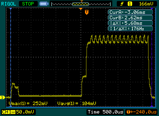
One of the cool things about having a digital scope is that you can take screenshots and post them in blogs :). I wanted to check how a Funky v2 was behaving, so hooked one to measure its current consumption using the voltage drop over a resistor (supposedly 10 ohm, but my multimer measures it as 12 ohm, probably I’ve got a 10% tolerance one).
Analyzing the footprint showed that I had insanely long delay when waiting for the ADC to settle when doing the battery level readout. Reduced that to 2ms and now it looks better. Power consumption tops to 25.2mA during the actual transmission (the second part of the trace). The wake up and battery level measurement is also visible, this is the first ‘bump’ in the trace:
So the whole thing lasts 5.68ms and the averaged power consumption is 10.4mA – this can be used for battery life calculators like this one. Odd thing is that these calculations are never true, I can never get in real life the predicted battery life.


I have no idea how to (correctly) use an oscilloscope, so I cannot reproduce your readings: I thought the y axis was the voltage (as shown in the bottom line: Vmax and Vavg) – so how do you get the current values from that?
Hi,
I have two day experience with oscilloscopes too. Basically you measure the current consumption based on the drop of voltage across a resistor in series to the power supply. Typically a 10Ohm would be used for easy calculation. From there it is Ohm’s law I=V/R or I=0.252/10 –> I=0.0252A or 25.2mA.
Does that make sense?
Well, at least for me, that makes sense. (But unfortunately, I don’t know whether this setup a “valid” method for measuring the current in this case (as said, sounds good to me, but depends on powersupply and so on!?)