
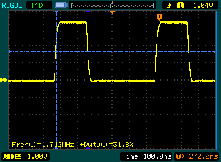
Timer 4 on the ATMega32U4 is a high speed one, but I have never tried it out before. Now that I have a scope, I decided to toy with it. It can work from the internal PLL, meaning some really high frequencies can be achieved. I managed to get up to 8Mhz, but probably more can be achieved with setting the PLL to even higher frequency. I tried out frquencies from 10Hz to 8Mhz. Anything above 700Khz is less accurate (or at least I couldn’t make it better), below that the frequency generated is pretty well matched. Here are couple tests with 1.712Mhz 33%Duty:
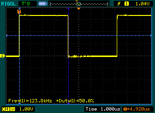
123456hz, 50% Duty:
So overall interesting experiment, I am not sure if it has any practical value other than testing my o-scope. Here is my code, if someone wants to try it out, I tested it on a Funky v2:
#define TIMER4_RESOLUTION 1023UL
#define PLL_FREQ 48000000UL

unsigned long pwmPeriod = 0;
ISR(TIMER4_OVF_vect) {}

void enable_intr(){
    TIMSK4 = _BV(TOIE4);
}

void disable_intr(){
    TIMSK4 = 0;
}

void initialize(unsigned long freq) {

    /* Init the internal PLL */
   PLLFRQ = _BV(PDIV2);
   PLLCSR = _BV(PLLE);
   while(!(PLLCSR & _BV(PLOCK)));
   PLLFRQ |= _BV(PLLTM0); /* PCK 48MHz */

   TCCR4A = (1<<PWM4A);
   TCCR4E = (1<<ENHC4);
   TCCR4D = (1<<WGM40); //set it to phase and frequency correct mode
   TCCR4C = 0;
   setPeriod(freq);
}
void setPwmDuty(unsigned int duty) {
   unsigned long dutyCycle = pwmPeriod;
   dutyCycle *= duty;
   dutyCycle >>= 9;
   TC4H = (dutyCycle) >> 8;
   OCR4A = (dutyCycle) & 255;
}

void start() {
  TCCR4A |= _BV(COM4A1);
}
void stop()  {
  TCCR4A &= ~(_BV(COM4A1));
}

void setPeriod(unsigned long freq)  {
unsigned long cycles = PLL_FREQ / 2 / freq;
unsigned char clockSelectBits = 0;

        if (cycles < TIMER4_RESOLUTION) {
		clockSelectBits = _BV(CS40);
		pwmPeriod = cycles;
	} else
	if (cycles < TIMER4_RESOLUTION * 2) {
		clockSelectBits = _BV(CS41);
		pwmPeriod = cycles / 2;
	} else
	if (cycles < TIMER4_RESOLUTION * 4) {
		clockSelectBits = _BV(CS41) | _BV(CS40);
		pwmPeriod = cycles / 4;
	} else
	if (cycles < TIMER4_RESOLUTION * 8) {
		clockSelectBits = _BV(CS42);
		pwmPeriod = cycles / 8;
	} else
	if (cycles < TIMER4_RESOLUTION * 16) {
		clockSelectBits = _BV(CS42) | _BV(CS40);
		pwmPeriod = cycles / 16;
	} else
        if (cycles < TIMER4_RESOLUTION * 32) {
		clockSelectBits = _BV(CS42) | _BV(CS41);
		pwmPeriod = cycles / 32;
	} else
        if (cycles < TIMER4_RESOLUTION * 64) {
		clockSelectBits = _BV(CS42) | _BV(CS41) | _BV(CS40);
		pwmPeriod = cycles / 64;
	} else
        if (cycles < TIMER4_RESOLUTION * 128) {
		clockSelectBits = _BV(CS43);
		pwmPeriod = cycles / 128;
	} else
        if (cycles < TIMER4_RESOLUTION * 256) {
		clockSelectBits = _BV(CS43) | _BV(CS40);
		pwmPeriod = cycles / 256;
	} else
        if (cycles < TIMER4_RESOLUTION * 512) {
		clockSelectBits = _BV(CS43) | _BV(CS41);
		pwmPeriod = cycles / 512;
	} else
        if (cycles < TIMER4_RESOLUTION * 1024) {
		clockSelectBits = _BV(CS43) | _BV(CS41) | _BV(CS40);
		pwmPeriod = cycles / 1024;
	} else
        if (cycles < TIMER4_RESOLUTION * 2048) {
		clockSelectBits = _BV(CS43) | _BV(CS42);
		pwmPeriod = cycles / 2048;
	} else
        if (cycles < TIMER4_RESOLUTION * 4096) {
		clockSelectBits = _BV(CS43) | _BV(CS42) | _BV(CS40);
		pwmPeriod = cycles / 4096;
	} else
        if (cycles < TIMER4_RESOLUTION * 8192) {
		clockSelectBits = _BV(CS43) | _BV(CS42) | _BV(CS41);
		pwmPeriod = cycles / 8192;
	} else
        if (cycles < TIMER4_RESOLUTION * 16384) { 		clockSelectBits = _BV(CS43) | _BV(CS42) | _BV(CS41) | _BV(CS40); 		pwmPeriod = cycles / 16384; 	}  /*else    		clockSelectBits = _BV(CS43) | _BV(CS42) | _BV(CS41) | _BV(CS40); 		pwmPeriod = TIMER4_RESOLUTION - 1; */	         TCCR4B = clockSelectBits;             TC4H = pwmPeriod >> 8;
        OCR4C = pwmPeriod;

    }

void setup() {

pinMode(13, OUTPUT);
digitalWrite(13,LOW);
initialize(123456);  // Frequency to generate in Hz
setPwmDuty(512);     // Duty cycle 0-1024, 1024 is 100%, 512 is 50%
start();

}
void loop(){
}
What pin should this output on? I tried it on a teensy 2.0 (atmega32u4) and can’t find any output on any pin.
If I can get this working it will be very useful for having the atmega clock an external sound chip.
Thanks!
Digital 13 pin only
Ah I think you mean pin 13 on your actual Funky v2 board, right? OC4A (PC7) is what you have pin 13 on your board connected to. On the teensy 2.0 it is C7 or Arduino 10. I will look for the signal there.
Thanks!
Hi i tried the code you posted on arduino leonardo. It compiles well but i lose connection to leonardo and it is not recognized by windows. I need to upload a new empty sketch via reset to get arduino back. Please can you help.
Try pressing the reset button at the time of sketch upload, this should work
I try this on Pro Micro (SparkFun) and transforms my device into a brick, as mentioned before by Timi above.
To restore my Pro Micro, I had to make the procedure listed here
https://learn.sparkfun.com/tutorials/pro-micro–fio-v3-hookup-guide/troubleshooting-and-faq#ts-reset
That is the port assignment and reset with a regular code with more steps so it could help.
Do you know why this code will not work with ProMicro? It is very compatible with everything,
The piout could be found on
https://learn.sparkfun.com/tutorials/pro-micro–fio-v3-hookup-guide/hardware-overview-pro-micro
Maybe if I reassign the pin to pin10 (PWM) ? I try that and still bricks my board. Any other suggestion?
Thank you,
Gaston