
[Edit] Make sure to check my much more advanced example here
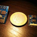
The ESP8266 System-on-chip (SoC) has recently came out of nowhere and has been taking by storm the IoT DIY world. It is a $4.50 Wi-Fi capable chip that has remarkable specs, obsoleting overnight a number of similar products that are out there. The price factor, availability of SDK and a fast growing community make this chip quite attractive.
The most common usage for the chip so far has been to interface it to MCU and utilize the AT commands that are available in the default firmware, however that is quite an abuse of the power under the hood of the ESP8266. I’ve decided not to use external MCU and utilize the chip itself for a proof-of-concept project:
The project shall be able to
- Run a HTTP daemon
- Be configurable through web interface
- Provide web UI for switching on/off a LED connected to GPIO pin
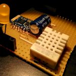
- Provide web UI for reading a temperature+humidity sensor (DHT22)
There are few different versions of the breakouts available, most popular is the DIP version . However that version only has GPIO0 and GPIO2 routed to the header, so I also purchased the SMD version that has all the pins available. I have made couple interface strip-board PCBs so that I can interface the modules with a “pure” 3.3V FTDI cable:
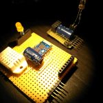
The capacitor is to provide extra juice during active WiFi operations as the FTDI cable can only provide ~50mA while bursts of Wifi may be in the area of ~200mA. I used a 1000uF capacitor on the PCBs, but a 470uF also worked with no issues.
The SMD version is more interesting, as more of the GPIO pins are available:
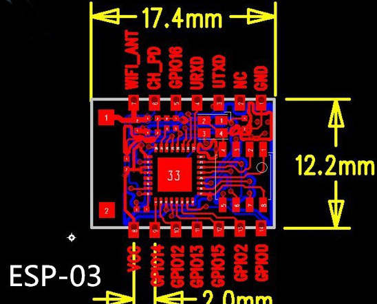
To program new firmware on the ESP-03 the following pin connections must be done:
1. CH_PD to VCC
2. GPIO02 to VCC
3. GPIO00 to GND
4. GPIO15 to GND
For normal start CH_PD to VCC and GPIO15 to GND.
Thanks to the great community at esp8266.com that project is possible with minimal effort. The esp8266 httpd project published by Sprite_tm is an incredible piece of art that allows you to run a HTTP server and simple CGI on the chip. One of the challenges with embedded systems is the difficulty in connection/misc configuration. The project overcomes this by providing a web UI that one can use to manage the settings.
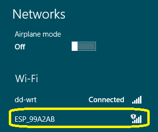
If upon startup the chip isn’t able to connect to a WiFi hotspot using the saved credentials, it would automatically activate Access Point mode and you’ll be able to see “ESP_XXXXXX” where XXXXXX are the last 6 digits of the esp8266’s MAC address:
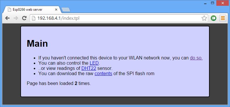
You can connect to that open AP and navigate to http://192.168.4.1 to scan for wifi networks and enter the connection password:
Main page
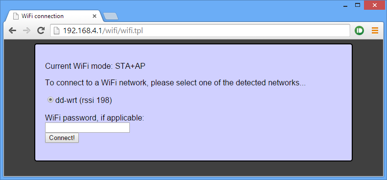
WiFi settings page:
 The password will be saved and from now on the module will automatically connect to that network. You don’t need to do that, all the other functions are fully accessible without the module being connected to the Internet. I can think of at least dozen use cases where that could be useful. However for my particular project, I’d need the module to be available over the Internet.
Once connected to a network, you’ll probably be wondering what the IP address of the module is. The module uses DHCP, so the address of the module will vary. You can set up a static IP lease if your router allows it, or find the ip address every time you need to use it.
I use the following linux command to find the IP address of the ESP8266 modules connected to my network:
sudo arp-scan –retry 7 –quiet –localnet –interface=wlan0 | grep -s -i 18:fe:34
Navigating to the IP address of the module opens the same UI we were seeing before, same functionality as well. Below are the LED control and DHT22 sensor reading pages:
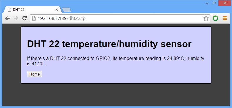
I have a LED connected to GPIO13, but that could be a relay for example.
The DHT22 page is a simple html page, but it could just be a JSON string that can be periodically polled by http://freeboard.io/ dashboard or Node-RED flow for example. The module can also be set to push the readings to a pre-configured URL at some interval; a UI interface could be set to configure destination URL, push frequency and other settings: all in my to-do list. DHT22 code by fasmide.
MQTT support on the esp8266 is a matter of time, so the web configurable settings and MQTT support will make the module excellent choice for a number of home automation tasks.
On the weaknesses side is the power consumption. During active WiFi operations it can draw up to 250mA, making battery mode quite challenging. I’ll probably stick to my ATTiny84+RFM12B nodes for low power battery operated tasks, those last more than a year on single AAA battery with a boost regulator.
The application source code is available here: app, includes the binaries so you can directly flash those without having to set up the SDK environment:
sudo ./esptool.py –port /dev/ttyUSB0 write_flash 0x00000 firmware/0x00000.bin
sudo ./esptool.py –port /dev/ttyUSB0 write_flash 0x40000 firmware/0x40000.bin
sudo ./esptool.py –port /dev/ttyUSB0 write_flash 0x12000 webpages.espfs
As a conclusion I’d say that this chip is a game changer. I am loving it and will be using it in my next home automation projects a lot.
Hi,
Great post, how about stability? I hear those esp8266’s are fairly buggy/unstable and have very short WiFi range.
Martin
I haven’t experienced crashes yet; seems pretty reliable to me. Range is pretty good for such a small module, I walked around the house with one in my hand and was getting pings ~20m away from the house..
I found my model 1 to have reasonable range, and my model 3 outperforms almost any other device I own in terms of keeping a connection stable (slower than any other device I have though). Haven’t used it long enough to say if it’s stable or not, but a lot of the software is a bit hard to get your head around.
You are awesome! Thanks for this!
Currently designing nodes on nrf2401+, but this chip could be all I need!?
Depends..if you need battery operated node, the nrf2401+ would still be the better choice
Pingback: Running a Web Server on the ESP8266 | Hackaday
Great post! Thanks for sharing the code, too.
Pingback: Running a Web Server on the ESP8266 | Ad Pub
Pingback: Running a Web Server on the ESP8266 |
not working for me
must there be something connected to GPIO 2 and 13 or HL levels for starting AP mode 192.168.4.1 ?
should there still be some reactions to AT commands because there aren’t.
funny thing is when i flash back to 9.2.2 i have a AP under that address but i get no answer to change settings of course.
could you please make one bin for 0x00000 ?
thank’s for any help
Hi,
GPIO15 needs to be LOW at all times. AT commands are eliminated from this firmware, so don’t expect any response. Still there is a lot of debug info on the serial @ 115K baud, so you may still be seeing interesting stuff there.
Here is a full bin:
http://harizanov.com/wp-content/uploads/2014/11/flash.zip
Hi Martin,
thanks for the bin file. esp8266_flasher.exe stopped at 99% and not exited but i hope it is still ok.
The only problem left is that i can’t bring it to join my WIFI AP. It finds my network but not joins it even if it is open.
The serial output is :
URL = /wifi/connect.cgi
Mallocced buffer for 52 bytes of post data.
Post data: essid=MAX&passwd=1111923669566041&connect=Connect%21
Is url index 10
findArg: essid=MAX&passwd=1111923669566041&connect=Connect%21
findArg: val MAX&passwd=1111923669566041&connect=Connect%21 len 3
findArg: essid=MAX&passwd=1111923669566041&connect=Connect%21
findArg: passwd=1111923669566041&connect=Connect%21
findArg: val 1111923669566041&connect=Connect%21 len 16
Conn 0x3fff42f0 is done. Closing.
URL = /wifi
Is url index 6
Conn 0x3fff47c8 is done. Closing.
Con req, conn=0x3fff4b60, pool slot 0
URL = /wifi/wifi.tpl
Is url index 9
Heatshrink compressed file; decode parms = b4
Con req, conn=0x3fff4d58, pool slot 1
URL = /style.css
Is url index 11
Heatshrink compressed file; decode parms = b4
Conn 0x3fff4d58 is done. Closing.
Con req, conn=0x3fff4ec8, pool slot 1
URL = /wifi/140medley.min.js
Is url index 11
Heatshrink compressed file; decode parms = b4
Conn 0x3fff4ec8 is done. Closing.
Con req, conn=0x3fff43e0, pool slot 1
URL = /wifi/wifiscan.cgi
Is url index 8
STA status = 3. Disconnecting STA…
Conn 0x3fff43e0 is done. Closing.
Con req, conn=0x3fff4830, pool slot 1
URL = /favicon.ico
Is url index 11
End of image.
/favicon.ico not found. 404!
when booting it still wants dd-wrt as AP and not my MAX
thank’s for helping me
Try this latest version:
http://harizanov.com/wp-content/uploads/2014/11/flash.zip
Hi,
it does not work 🙁
Try the binary I posted in the commentsCan you elaborate what doesn’t work? It works just fine here on my board
If you are interested in the range of these see this video :-
http://www.youtube.com/watch?v=7BYdZ_24yg0
In their test the ESP-01 version was reliable up to 500 metres.
With an external antenna over 1KM was achieved. With a dish antenna the line of sight distance was crazy!
Pingback: A temperature monitor for the ESP8266 | My Tech Weblog
Pingback: A new ESP8266 Day | My Tech Weblog
Hi,
Great post! I would like to run your example on ESP-01 using only the LED connected to GPIO 2. Is it possible?
The LED is hard-coded to GPIO13, only available on the SMD version of the ESP8266. You’ll need to re-compile and move the LEDs to another pin.
Great writeup, thanks! I have a few of these one the way now, will be fun to play with.
Cheers,
Johan
Hi,
i installed the image to my ESP01 and it works. Great.
i take the source to my virtal machine (virtual box) and it compiles without any errors. But when i flash my ESP01 nothing happens.
i use:
ESP8266_lubuntu_20141021.ova
esp_iot_sdk_v0.9.2_14_10_24
copy the source to the app directory and run make. this works without any errors.
then i flash 0x00000.bin and 0x40000.bin but nothing happens. on serlal i got no valid data.
Regards, Werner
Hi, what about webpages.espfs? it needs to be flashed as well to address 0x12000.
Serial is on baud 115K, it spits out tons of useful debug information.
You can run a comparison of the binaries from what I published and what you get when compiling, just to make sure all is set up correctly.
Drop a line here if you figure what went wrong so that others can use that knowledge.
Cheers!
thanks for reply,
i have it now tested on ESP01 and ESP03
i load your firmware to both modules.
0x00000.bin to 0x00000
0x40000.bin to 0x40000
webpages.espfs to 0x12000
i use the files from unzipped app.zip
then i reset the module and use hterm with 115200 baud to see what happens. i get some data but not readable
on ESP03 Pin GPIO15 is set to low. right?
Regards, Werner
Hi Martin,
i flashed the bin file from http://harizanov.com/wp-content/uploads/2014/11/flash.zip and this image works.
the images from your source not. is there a new version?
Werner
yes , this is an updated version. NEed to set up a Github repo sometime
Grab from here: http://harizanov.com/wp-content/uploads/2014/11/app1.zip
don’t forget to share if you add something useful, open source is what keeps this going 🙂
Martin
Hi Martin,
Sorry, but i do not understand why it is not working.
i flashed the 3 files (ready in the zip) and same happens as before. the single flash file works.
Werner
It’s very nice. I have not DHT22, but I’m firmware loaded into the ESP8266. I really connected to the server. Pity that ESP-01 has not GPIO13, so I did not blink LED. I had trouble with programming, ESP8266 stopped responding and just spewed meaningless data, but I finally made it standard program ESP8266_flasher_V00180902_03.
Thanks so much for a beautiful job
Glad you got it going; Recompile it to use alternative GPIO. I may some day find time to post a bin for ESP-01
Please recompile for the ESP-01, I do not have the coding knowledge to do so and it would be greatly appreciated! Thanks, Merry Christmas!
There is a newer, more stable version of the httpd running on the newer SDK; I’ll be patching my code to use the latest versions first and then see about ESP-01. Cheers!
Thank you so much! Your Work is greatly appreciated!
Hi,
i really like your project and tried to run it as you posted here.
But i have a Problem with the /wifi/wifi.tpl page
The ESP is “scanning …” but there are no availible networks.
And there is a difference between your screen and mine:
Yours is in the WiFi Mode: STA+AP
Mine is: SoftAP
Do you habe any idea, how i can switch to STA+Ap mode?
I tried using serial connection with coolterm and 9600baut, but i cannot get a connection …
Any ideas?
Kind regards, Yuri
the http daemon page on esp8266.com (linked in the post) mentions such issue, probably the watchdog kicks in if too many access points exits, it fails.
There will be updated version for the new SDK soon, hopefully these will be cleaned up then.
While it is running, try keeping GPIO0 low for 6-7 seconds then release
Hello Martin,
thats what i tried before, but on startup.
Now i did it while running and it worked for me.
Thx for your help!
If I connect to a network, do i have to restart, or is there a message which says, that i have connected to a network. Can i also connect to the ESP direct, or is that not possible anmyore?
I choosed my wlan, but it seems not to work. I can still connect to the ESP over its own AccessPoint.
kind regards
Pingback: Pár poznámek k ESP8266 » Retročip
Pingback: The Lodge | ESP8266 Links
Hi Martin,
I´ve been trying to use your bin’s, even the bin’s from the orignal project, but once I tried to get connected to the ESP_XXXXXX AP it says to me that it has WPA2-PSK as security type instead of open as you referred on your blog, any idea?
I was trying with the first source code link, Im going to try with the bins on your comment at November 28, 2014 at 7:56 pm and also with Werner’s at November 28, 2014 at 6:30 pm, by the way Im using ESP01, just exploring the web server.
That’s odd, and I don’t have explanation for it.. the code clearly puts the module into open mode, so I ‘m not sure why you are experiencing this. Did you try scanning with your phone, just to confirm that both laptop and phone see it as WPA2-PSK?
Could it be that yu previously set your ESP8266 into protected mode and now it is re-using these settings?
Thanks for your reply Martin, yep, I think something like that was happening, kind of new mode and old mode being mixed, a little advice, not always worked in this way but maybe could help to anyone in my case, after flashing the code I disconnected GPIO0 then power off the ESP01, then power on ESP01 and nothing happens, I have to connect RST pin to VCC for a few seconds and then Voila!! the SSID of the ESP was there!!, thats great!! now I want to modify the html files but Im getting some problems trying to make webpages.espfs, Im using eclipse luna SDK, Im researching…
Nice job! I have it running smoothly on an ESP-03. I would like to use all the rest of the available GPIO pins but am having trouble recompiling it. Can you please provide an explanation on how to add more GPIO pins to your example LED webpage?
This would be pretty straight forward
1) modify cgi.c’s cgiLed and tplLed functions to handle more than one pin (basically requires copy/pasting)
2) modify io.c’s ioInit and ioLed to handle the additional pins
3) modify the led.tpl to allow controlling more than one pin
that should do 🙂
Martin
To be on the same page, can you please point at the guide how to set up the compiler, sdk and libraries the same way you did.
I’d recommend to use a slightly different approach than what I originally did. I myself have changed my setup according to this guide: https://github.com/esp8266/esp8266-wiki/wiki/Toolchain
then follow carefully the first post here:
http://www.esp8266.com/viewtopic.php?f=6&t=376
It is downhill after you set up the environment.
Hello Martin,
Thanks for your work.
I succes to clean the project and compile again files.
But i don’t find the way to regenerate ‘webpages.espfs’ file.
Could you share this information ?
Best regards, Stéphane
I find : make webpages.espfs
I use “make htmlflash” to build these
Hi,
your project is awesome!
Please tell us how to do the layout and please create a howto. I want to use it with my raspberry to do house automatisation.
Thanks in advance
cawi
Hi,
probably won’t be doing a how-to because something much bigger is cooking. Check my twitter posts to keep up
But what about a simple wiring/layout sketch? Would be nice 🙂
Pingback: WiFi IoT 3 channel relay board with MQTT and HTTP API using ESP8266 | Martin's corner on the web
Pingback: Making Something Useful With The ESP8266 | Hack The Planet
Pingback: Making Something Useful With The ESP8266 | 0-HACK
Hi Martin,
your project works like a charm – i love it. i runs without problems on my esp-01 after flashing the binaries with the esptool using OS X Yosemite. However i am facing some problems with my FTDI adapter. After a second flash run i can now see the debugging information.
Is it right that the AT-Codes do not work or is this due to my Serial2USB Adapter?
Keep rocking, Ben
Hi,
This firmware doesn’t have the AT commands set, those are stripped out to make room.
Hey,
good to know. I guess the same is true for the original esphttpd code from sprite_tm, which is the base for your code?
Yes, exactly..
Pingback: ESP8266 More Web Links | Zuzebox's Blog
Hi,
is it possible to send DHT22 data to remote server (calling remote URL) ?
If it’s planned function do you know ETA ?
Thanks
I have a broadcast deamon that does a HTTP GET to URL of your choice, currently posting to thingspeak.com, but can be anything as it is configurable. So this feature will be available in the final product when I release it, ETA seems to be around March
Great job! I can’t wait 🙂
One more question … will be possible to connect other components such as BMP180, DS18B20 etc. ?
Thank you
Hi Martin,
Could you please tell me what connections need to be made in order to
#1 upload firmware
#2 normal use
From your original post, couldn’t understand what’s the difference (or is it the same?). Beside those connections that you aforementioned, we also have to connect the TX->RX and RX->TX, right? Anything else?
Thanks
Forgot to say that I’m talking about an ESP-03
Pin Firmware update mode Firmware run mode
CH_PD High High
GPIO0 Low High
GPIO2 High High
GPIO15 Low Low
Thanks for your reply.
On the original post, you say “For normal start CH_PD to VCC and GPIO15 to GND.”
So, I suppose you wanted to say “For normal start CH_PD to VCC and GPIO15 to VCC”.
Correct?
Sorry for the confusion, the original post has it correct. I adjusted my answer so that no-one else gets confused as well
Hello Martin.
Which toolchain and SDK version are you using? Server binaries works like a charm, but i cannot compile it from source.
I’ve installed xtensa toolchain according to this tutorial: https://github.com/esp8266/esp8266-wiki/wiki/Toolchain. changed PATH in Makefile, and then, when im’ trying to compile project, i’ve got a lot of that kind of errors:
LD build/httpd.out
/opt/Espressif/ESP8266_SDK/esp_iot_sdk_v0.9.3/lib/libmain.a(app_main.o): In function `read_macaddr_from_otp’:
(.irom0.text+0x7c): undefined reference to `wDev_ProcessFiq’
There are many more similar, but i won’t spam that comment. I’m able to compile examples from related tutorial without any problems.
Hi,
check if the LIBS line in the Makefile contains pp
# libraries used in this project, mainly provided by the SDK
LIBS = c hal gcc phy pp net80211 wpa main lwip ssl
Had the same issue, adding pp to LIBS helped, Thanks
Hi, very great post, thank you.
Can you please help me on following questions:
– how can I turn off AP mode permanently?
– additional DHT22 page text output only (for parsing with gnuplot 😉
– set static IP for station mode
Thanks
DJ
Something like this will turn off the AP mode and set static IP:
struct station_config stationConf;struct ip_info info;
wifi_set_opmode(STATION_MODE); // Force Station mode
wifi_station_set_auto_connect(FALSE);
os_memset(&stationConf, 0, sizeof(struct station_config));
os_sprintf((char *)stationConf.ssid, "%s", "your SSID");
os_sprintf((char *)stationConf.password, "%s", "your pass");
info.ip.addr = ipaddr_addr("192.168.1.199");
info.netmask.addr = ipaddr_addr("255.255.255.0);
info.gw.addr = ipaddr_addr("192.168.1.1");
wifi_set_ip_info(STATION_IF, &info);
wifi_station_set_config(&stationConf);
modify cgi.c to output the desired DHT22 text
Thanks. modifying cgi.c ( adding new function txtDHT22 ) and user_main.c ( {“/dht22.txt”, txtDHT22, NULL}, ) worked fine.
I saw in your code you have already setup something what I want: turnig off the AP mode when connection was succeeded (after 4 seconds?).
Is there anywhere a check when Wifi is lost? So trying to reconnect somehow? In my tests today I lost Wifi and there was no auto – reconnect. After restarting the modul everything was fine again.
Hi, I love what you are doing. Have bought a bunch of ESP-01 modules and have some interesting plans like yourself. Im far far behind you in terms of programming skill though.
I have this firmware: http://harizanov.com/wp-content/uploads/2014/11/app.zip
I have flashed all three files,
python esptool.py –port /dev/cu.HC-06-DevB write_flash 0x00000 /Users/amelvin/git/esptool/app-2/firmware/0x00000.bin
python esptool.py –port /dev/cu.HC-06-DevB write_flash 0x40000 /Users/amelvin/git/esptool/app-2/firmware/0x40000.bin
python esptool.py –port /dev/cu.HC-06-DevB write_flash 0x12000 /Users/amelvin/git/esptool/app-2/webpages.espfs
and it was successful… but i get this messages when i connect at 115200 baud.
The module with NodeMCU and the original firmware were able to connect just fine to the wifi network.
Ready
mode : sta(18:fe:34:9d:8d:41)
add if0
scandone
no dd-wrt found, reconnect after 1s
reconnect
scandone
no dd-wrt found, reconnect after 1s
.l|.l|.|b.ònlnìb.ppòn…n|l.ònn.l..l…nr.l.pòn.à..n|.ònn.l..l…nrl.pòn.à..n|l..ònn.l..l…nrì.ì.l|.l|.|b.ònlnìb.ppòn…n|l.ònn.l..l…nr.l.pòn.à..n|.ònn.l..l…nrl.pòn.à..n|l..ònn.l..l…nrì.ìHttpd init, conn=0x3ffea200
Ready
mode : sta(18:fe:34:9d:8d:41)
add if0
scandone
no dd-wrt found, reconnect after 1s
reconnect
scandone
no dd-wrt found, reconnect after 1s
reconnect
.l|.l|.|b.ònlnìb.ppòn…n|l.ònn.l..l…nr.l.pòn.à..n|.ònn.l..l…nrl.pòn.à..n|l..ònn.l..l…nrì.ìHttpd init, conn=0x3ffea200
Ready
mode : sta(18:fe:34:9d:8d:41)
add if0
scandone
no dd-wrt found, reconnect after 1s
reconnect
scandone
no dd-wrt found, reconnect after 1s
reconnect
scandone
no dd-wrt found, reconnect after 1s
reconnect
scandone
no dd-wrt found, reconnect after 1s
reconnect
scandone
no dd-wrt found, reconnect after 1s
reconnect
scandone
no dd-wrt found, reconnect after 1s
reconnect
scandone
no dd-wrt found, reconnect after 1s
reconnect
Pingback: Añadir conexión Wifi a Arduino con ESP8266 « El Cacharreo.com