
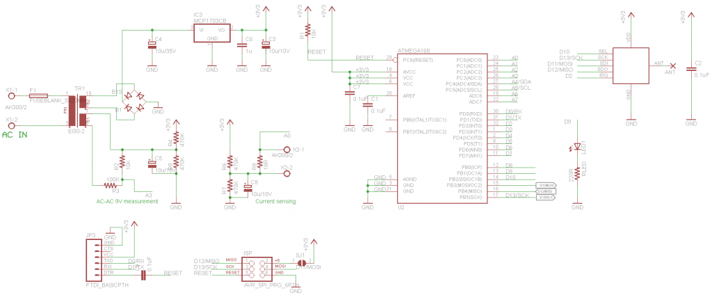
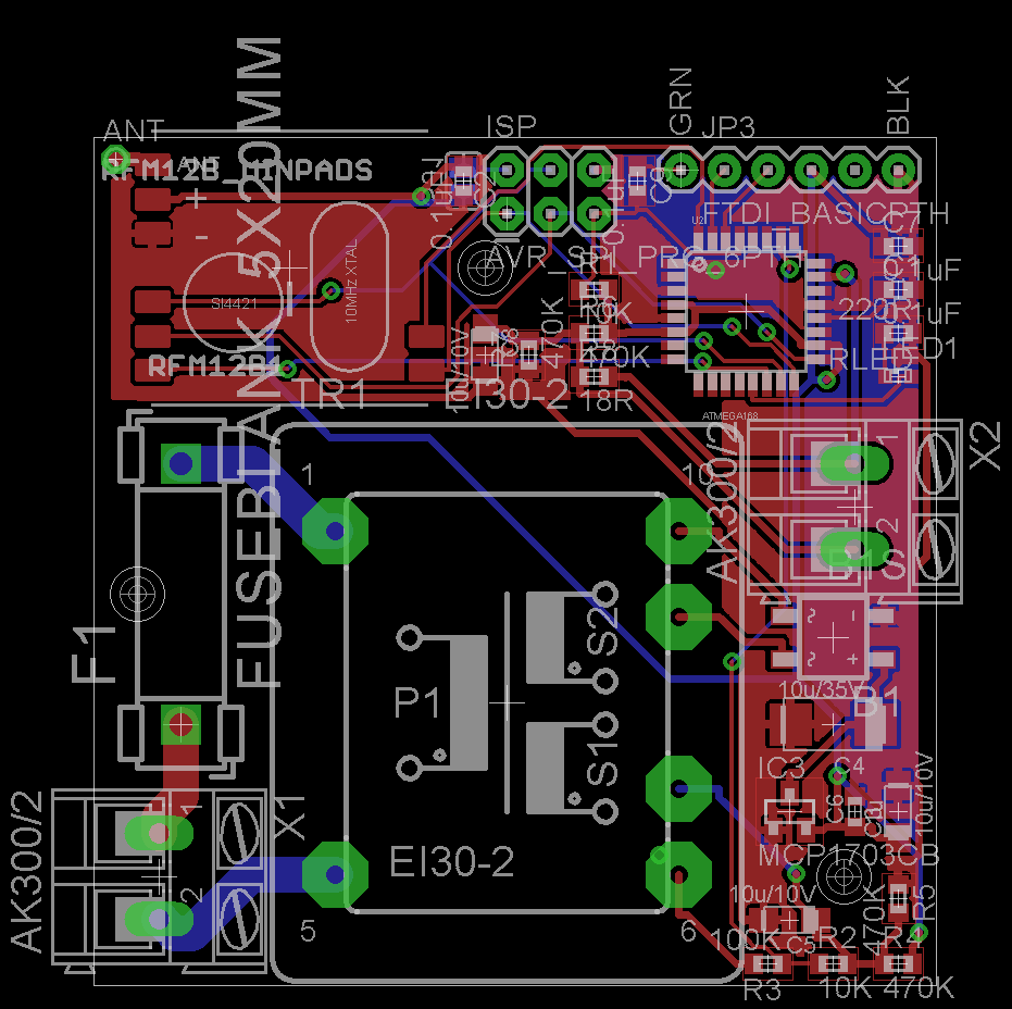
I seem to be doing power monitoring projects a lot, started with this one, then moved on to this, then this and now I am again putting up a power monitor.. This particular will be using a small transformer with two secondary windings: one will be used to power the circuitry and the other for voltage sensing. PCB is 5*5 cm and will have screw terminals for 230V and a current sensor. On-board is a RFM12B module that will transmit the readings to a base station. The processor is an Atmega328 running on its internal RC oscillator. The circuitry will run on 3.3V to simplify things. Here is how it is taking shape, comments are welcome:
Great!!
What about to add a rely? something like the new Belkin Wemo Insight Switch,
You could control RF power sockets with the RFM12B module, I have few posts on the subject. Adding relays will make the board larger, I aimed at max 5*5 cm here so the PCB manufacturing is cheap.
Hi Martin,
Cool idea indeed, but would you have space to fit an on-board current sensor (eg CT1248 from electrohms) in stead of the screw terminals ? I find the current sensors used in the emonTX quite bulky, especially if you’re monitoring just one home appliance.
Interesting, the sensor you suggest could be added as a ‘shield’ on a breakout board instead of using the screw terminal. The cable still needs to go thru it, and the transformer is quite bulky (rises high above the PCB).
Martin,
Another interesting project. Thanks for sharing
I am currently looking at miniature transformers 22x22x15mm for powering a central heating controller. Basically an ATmega328, RFM12B and up to 4 relays. It’s an extended version of my WiNode 4, which has RTC, SRAM and microSD.
I am interested in your Funky 3 as individual room or tank/pipe wireless temperature sensors.
It is very disappointing that the RFM12B is being discontinued. It has been a very useful device, and now perhaps we will have to move to the nRF2401.
regards
Ken
Thanks Ken,
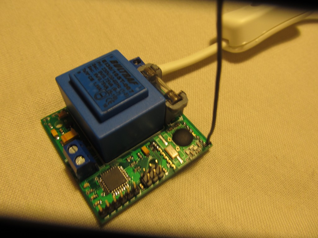
here is a picture of it materialized:
The transformer you mention sounds pretty exciting, does it pack enough power to be able to switch relays? Or you plan to overcome that with some huge capacitors? In any case, this is a nice product niche that I too have recognized, see my hot water tank IoT project. I have it subscribe to an emoncms feed and behave according to its value.
The Funky v3 may be an overkill just do temperature monitoring, I’d go for something cheaper and simpler like the Funky v1 to do this.
I too am upset regarding the planned decommissioning of the community favourite RFM12B, I have stocked a ton for my future projects 🙂
Cheers
Pingback: The YAPM PCB is done | Martin's corner on the web
Hi Martin,
Quite a bit of informative stuff you post here. Borrowing your ideas, I plan to build one (using Arduino Uno to start with).
I have one query about the this power monitor. You’ve used a step-down transformer for voltage measurement; how accurate is it? Others have noted that a transformer introduces significant phase/amplitude errors. Is there a specific requirement (other than voltage/VA rating) for the transformers used?
Thanks,
-preetam
Using a transformer is by no means ideal, it introduces a distortion and shift in the voltage waveform, but is a quick and dirty (and cheap) way to achieve satisfactory level of precision for the home user. I have another project that was sampling the AC waveform directly after a voltage divider, look it up as well. The focus for this particular project was to make it relatively cheap, few % inaccuracy was acceptable
oh and another idea in this area: http://openenergymonitor.org/emon/node/2379
Martin,
Thanks for the pointer! This two-transformer approach seems easy too.
Yes, I agree your point about cheap design for home use.