
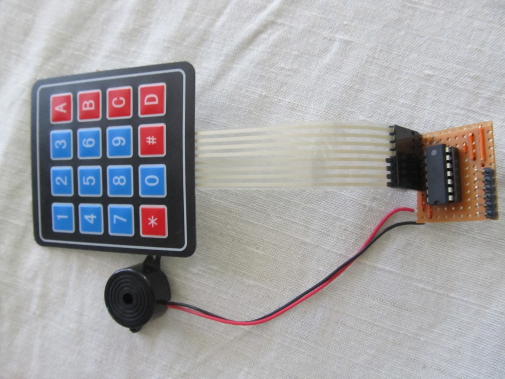
I bought one of these keypads off ebay few days ago, and decided to try it out.
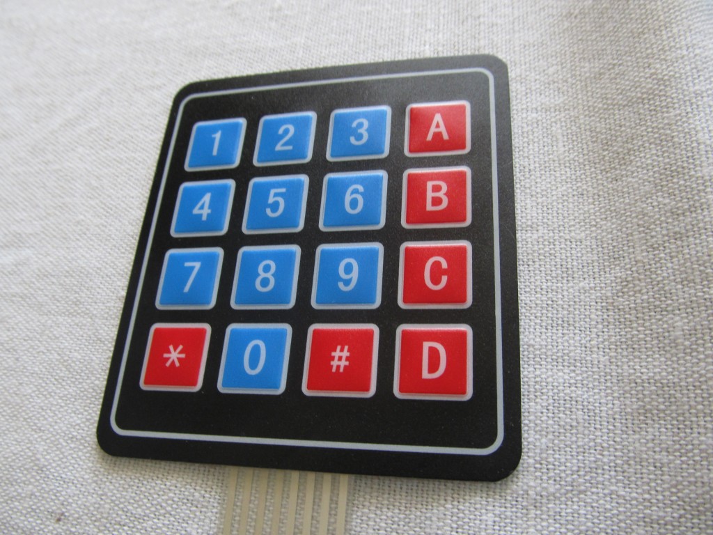
These work pretty straight-forward, you have 8 pins – 4 for rows and 4 for columns. When you press a button, it creates contact between the respective row and column. Still, you need 8 pins to drive it, so I decided to use an Attiny84 to do the reading and output the result to a serial output @ 9600 baud. This way I can use the keypad with only one pin (RX) and of course VCC and GND. Further more, for low power applications, I wanted the ATtiny84 to sleep and only wake upon key press. This will make this solution viable for battery operated nodes, I use pin change interrupts to trap keys. The ATtiny84 provides a feedback pin that goes HIGH for 100ms when a button is pressed, this can be used for visual confirmation via a LED, or a piezo buzzer or to wake up a sleeping host system so it can read the key.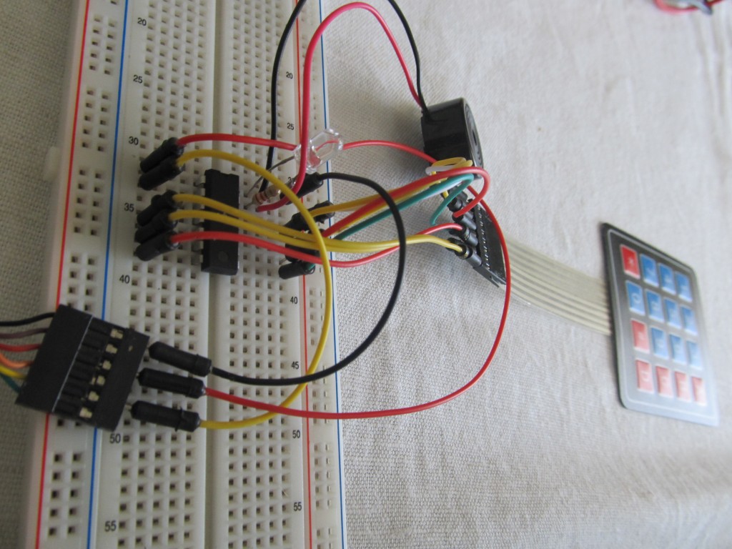
Power consumption when waiting for a key press cannot be measured with multimer as it is below any scale, the datasheets states the ATtiny84 consumes 0.1 µA in Power-Down Mode, so you can run it for ages.
My code is simple:
#include < avr / sleep.h >
#include <Keypad.h> // http://playground.arduino.cc/code/Keypad
#include <PinChangeInterrupt.h> // http://code.google.com/p/arduino-tiny/downloads/list

/*
Edit PinChangeInterrupt.h to allow 4 PinChange handlers:

#if defined( __AVR_ATtinyX4__ )
#define NUMBER_PIN_CHANGE_INTERRUPT_HANDLERS (4)
#define NUMBER_PIN_CHANGE_INTERRUPT_PORTS 2
#endif

*/

#ifndef cbi
#define cbi(sfr, bit) (_SFR_BYTE(sfr) &= ~_BV(bit))
#endif
#ifndef sbi
#define sbi(sfr, bit) (_SFR_BYTE(sfr) |= _BV(bit))
#endif

/*
                     +-\/-+
               VCC  1|    |14  GND
TX        (D0) PB0  2|    |13  AREF (D10)
          (D1) PB1  3|    |12  PA1 (D9)
             RESET  4|    |11  PA2 (D8)
INT0  PWM (D2) PB2  5|    |10  PA3 (D7)
      PWM (D3) PA7  6|    |9   PA4 (D6)
      PWM (D4) PA6  7|    |8   PA5 (D5) PWM
                     +----+
*/

const byte ROWS = 4; //four rows
const byte COLS = 4; //four columns
char keys[ROWS][COLS] = {
  {'1','2','3','A'},
  {'4','5','6','B'},
  {'7','8','9','C'},
  {'*','0','#','D'}
};
byte rowPins[ROWS] = {9, 8, 7, 6}; //connect to the row pinouts of the keypad
byte colPins[COLS] = {5, 4, 3, 2}; //connect to the column pinouts of the keypad

Keypad keypad = Keypad( makeKeymap(keys), rowPins, colPins, ROWS, COLS );

void wakeUp() {}

void setup(){
    Serial.begin(9600);
    pinMode(10,OUTPUT);
    digitalWrite(10,LOW);
    PRR = bit(PRTIM1); // only keep timer 0 going
    ADCSRA &= ~ bit(ADEN); bitSet(PRR, PRADC);   // Disable the ADC to save power
}

void loop(){

  pinMode(9,INPUT);
  digitalWrite(9,HIGH);  //Internal pull-up
  attachPcInterrupt(9,wakeUp,FALLING); // attach a PinChange Interrupt on the falling edge

  pinMode(8,INPUT);
  digitalWrite(8,HIGH);  //Internal pull-up
  attachPcInterrupt(8,wakeUp,FALLING); // attach a PinChange Interrupt on the falling edge

  pinMode(7,INPUT);
  digitalWrite(7,HIGH);  //Internal pull-up
  attachPcInterrupt(7,wakeUp,FALLING); // attach a PinChange Interrupt on the falling edge

  pinMode(6,INPUT);
  digitalWrite(6,HIGH);  //Internal pull-up
  attachPcInterrupt(6,wakeUp,FALLING); // attach a PinChange Interrupt on the falling edge

  pinMode(5,OUTPUT);
  digitalWrite(5,LOW);
  pinMode(4,OUTPUT);
  digitalWrite(4,LOW);
  pinMode(3,OUTPUT);
  digitalWrite(3,LOW);
  pinMode(2,OUTPUT);
  digitalWrite(2,LOW);

  set_sleep_mode(SLEEP_MODE_PWR_DOWN);         // Set sleep mode
  sleep_mode();                                // Sleep now
  sleep_disable();
  detachPcInterrupt(9);
  detachPcInterrupt(8);
  detachPcInterrupt(7);
  detachPcInterrupt(6);

  pinMode(5,INPUT);
  pinMode(4,INPUT);
  pinMode(3,INPUT);
  pinMode(2,INPUT);

  pinMode(9,INPUT);
  pinMode(8,INPUT);
  pinMode(7,INPUT);
  pinMode(6,INPUT);

  unsigned long ctime=millis();

  while(millis()-ctime<1000) {
  char key = keypad.getKey();

  if (key){
    digitalWrite(10,HIGH);
    delay(100);    //Wait for the host to wake/become ready
    Serial.print(key);
    Serial.flush();
    digitalWrite(10,LOW);
    ctime=millis();
  }

  }

}
See it in action, this is a test with a FTDI cable and PuTTY terminal program capturing the output.
So, it is really easy to use on Arduino, Raspeberry PI’s UART and so forth.
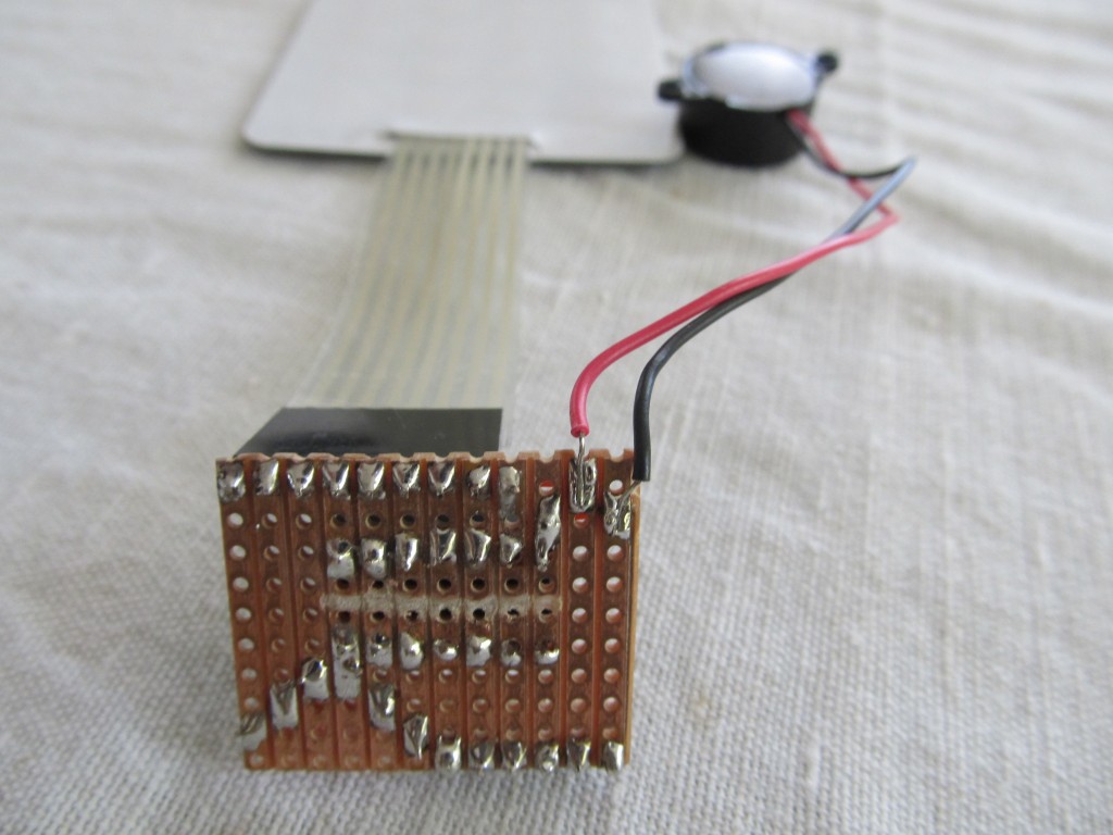
I can see how this will end up as a product in the shop 🙂
Very nice idea on setting a Attiny84 in between the keypad and the Arduino.
I think I will apply it to a keypad I have around.
I see there is no XTAL on the pcb, could you explain how you are doing this? I guess using the internal clock? I would like to know if you could explain the code lines for this.
Thanks and great work !
Yes, it is running off the internal oscillator. That by itself also contributes to cutting down the power consumption, plus simplifies the whole setup. It is enabled by setting the fuses
low_fuse=0x62
high_fuse=0xD7
extended_fuse=0xFF
using an ISP programmer
Pingback: Logging manualy entered values to emonCMS using keypad | Martin's corner on the web
Pingback: Keypad as USB keyboard | Martin's corner on the web