
I have a Paradox home security system and I have long wanted to interface with it. I am most interested in its status (armed, disarmed) and the zone statuses. I can use the alarm status to send myself SMS when the system becomes armed/disarmed or the alarm goes on. Zone statuses would provide me knowledge about indoor movement and help with automation tasks. I need R/O access to these, not bi-directional access, that makes the whole setup much easier. Of course Paradox offers product to do exactly this, but where is the joy of hacking things?
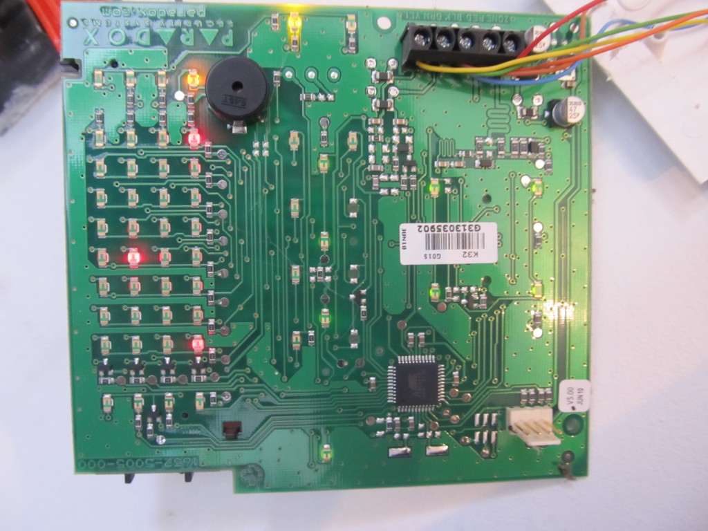
So I wasn’t sure where to start with and took apart one of the keypads that is located in my garage. I was expecting the alarm to kick in, but it turns out there is no tamper detection on these. Duh. I checked the keypad’s wiring and knew that I’d be looking at the green and yellow wires. The MCU is an ATMega16U4.
Hooked those to the oscilloscope to see this:
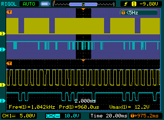
So obviously the yellow line is a clock one, going at 1Khz, 50% duty cycle. The green wire is the data. There are ‘packets’ of data with different sizes, these are clearly visible in the zoomed out window. Further inspection revealed that the data line sometimes transitions on falling and other times on rising CLK signal. I googled a bit and it turns out that this is a common approach with the DSC alarm systems, so basically it turns that this protocol is using the CLK line and then rising edge of CLK for keypad->panel and falling edge for panel->keypad communication. The signals are at 12V, so I need to bring these down a bit for Arduino levels. I will use a JeeNode v6 for this project as I can power it from the 12V line of the keypad, as its voltage regulator can handle 12V. I made two voltage dividers that will bring the CLK and DATA lines to 2.3V, pretty safe for the JeeNode running on 3.3V:
CLK ---- 20K ------- Arduino Pin
                |
               4.7K
                |
GND -------------
As software side, I put together this code (from various DSC keypad resources):
#include <JeeLib.h> // https://github.com/jcw/jeelib
#define myNodeID 23 // RF12 node ID in the range 1-30
#define network 210 // RF12 Network group
#define freq RF12_868MHZ // Frequency of RFM12B module
unsigned long lastread=0;
int datapin = 5;   // 4 on the uno; 1 on the tiny

int clockpin = 3;  // 2 on the uno ; 2 on the tiny
#define databytes 32
int data[databytes];
int datavalue = 0;
/*
D1 message:
D1 0 8 20 0 0 0 1C 4 1 A 9C 0 0 0 1 78
byte 12
if 9C, then ARMED
if 88, then about to become ARMED within 5 sec
if AA, then count-down to ARM is in progress
if E6, then system is armed in SLEEP mode
if B8, then system is about to become armed in SLEEP within 5 sec
if 86, system is about to enter SLEEP
18 is UNARMED
D0 messge:
D0 0 0 0 0 0 0 14 2 1 A C6 0 0 0 0 F0
byte 12 is the zones byte, yet to understand its structure
zone 25 on - A4 0b10100100
zone 25+13 - 4E
zone 13 on - 2C 0b00101100
nothing on =c6 0b11000110
*/
int bitcounter = 0;
int dataindex = 0;
int dataread=0;
int lastdataread = 0;
int startbit = 1;
boolean canprint =false;
boolean ignorepadding = true;
unsigned long lastprint = 0;
typedef struct {
unsigned int armstatus;
unsigned int zones;
} Payload;
Payload paradox;
#define rxPin 1
#define txPin 3
void setup() {
// define pin modes for tx, rx, led pins:
Serial.begin(115200);
pinMode(datapin, INPUT);
pinMode(clockpin, INPUT);
rf12_initialize(myNodeID,freq,network); // Initialize RFM12 with settings defined above
attachInterrupt(1, readbit, CHANGE);
data[0] = 0;
lastread = micros();
lastprint = millis();
}
void loop() {
unsigned long now = micros();
if((abs(now - lastread) >1000) && (abs(now - lastread) <10000) && canprint) {
byte havechange=0;
if(data[0]==0xD0){
if(data[11]!=paradox.zones) {
paradox.zones=data[11];
havechange=1;
}
}
if(data[0]==0xD1){
if(data[11]!=paradox.armstatus) {
paradox.armstatus=data[11];
havechange=1;
}
}
if(data[0]==0xD1 || data[0]==0xD0){
for(int i=0; i<= dataindex; i++){ Serial.print(data[i], HEX); Serial.print(' '); }
Serial.println();
}
if(havechange) {
rfwrite(); // Send data via RF
havechange=0;
}
dataindex = 0;
data[dataindex] = 0;
datavalue = 0;
bitcounter = 0;
startbit = 1;
ignorepadding = true;
canprint = false;
}
}
void readbit(){
lastread = micros();
int clkstate = digitalRead(clockpin);
if(1==1 ) { // watch for noise
if(clkstate == HIGH) {
if(!startbit){
if(dataindex != 1 || bitcounter!=0 || !ignorepadding){
data[dataindex] |= datavalue << (7-bitcounter);
datavalue = 0;
bitcounter++;
if(bitcounter==8){
dataindex++;
data[dataindex] = 0;
bitcounter = 0;
}
} else {
ignorepadding = false;
}
} else {
startbit -= 1; //eat startbits
datavalue = 0;
}
} else {
datavalue = !digitalRead(datapin);
}
canprint = true;
}
}
//--------------------------------------------------------------------------------------------------
// Send payload data via RF
//--------------------------------------------------------------------------------------------------
static void rfwrite(){
while (!rf12_canSend())
rf12_recvDone();
rf12_sendStart(0, ¶dox, sizeof paradox);
rf12_sendWait(0);
}
So this code would spit out these serial packets for me to analyze. I found out that the alarm arm status is contained in packets starting with 0xD1 and the zone information is in packets starting with 0xD0. While I could get definite values for the alarm status, the zone information doesn’t currently make sense to me. It is a single byte for all 32 zones, that bytes changes whenever a zone is open, but I can’t find its logic yet. So I am just recording it for now.
[eidt] that was a silly statement, you can’t possibly fit 32 zone on/off data in a byte. I will have to look deeper
Another odd thing is that the key presses are passed on un-encrypted, meaning that you can tap anywhere in the bus and ‘steal’ the arm/disarm codes. Pretty stupid of Paradox to allow that. Using the JeeNode’s radio module these can be transmitted wirelessly to a nearby logging station.
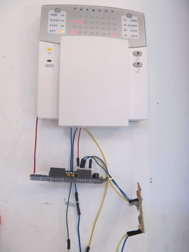
So basically my code transmits changes in the alarm status and raw zone information to a NaNode gateway, which in turn redirects this information to my EmonCms installation. I haven’t done so, but I plan to set a simple code to send me SMS whenever Alarm’s armed status changes.
As a TO-DO it remains for me to decode the zone information byte.
Hi there,
Great post, I currently have some more information about the protocol used. Please email me so we can get this Arduino interface fully implemented. 😉
I did some similar work on the security system in my house. I have a different model of security system but it sounds like it uses the same (or similar) DSC protocol. Maybe it will help you out.
Here’s a post about it:
http://sharpk60.blogspot.com/2012/07/security-node-demo.html
And the code:
https://github.com/sharpk/SecurityNode
That’s really nice, I want to do something like this 🙂
This is really interesting, I’ve always meant to have a look at my alarm system to figure out the protocol, this gives me a great head start, now just move it up the list of things to do ……so many things to do!
IP100 module won’t help much with what you are trying to achive.
It has javascript encumbered Web interface which you of course can parse each N seconds.
Other than that it has NEware server listening on port 10000, which implements some kind of native protocol iOS/Android iParadox app talks via.
But I never managed to get any information on the protocol itself.
Hi Alex,
I hope you still get notifications from this thread…
Are you quite well versed with the IP100? I want to write my own app for arming and disarming on iOS as it just takes too long via the “web” interface and I want to combine it with “scenes/scenarios” which their own app does not allow.
Regards
Paul
Pingback: » Alarme Paradox pas si sécurisé
Nice.
I tried to sniffer this system’s serial interface and found that one packet length is 37 bytes. The first 6 bytes are always the same. When zone status changes then the 9th byte is zone number. From 16th to 31th is reported zone’s name. What means other bytes I have no managed yet.
Another option you can look at is using the Paradox PRT3 Printer Module. Specifically for home automation. RS232 out and the manual gives you all the commands.
Unfortunately it only works on the EVO series Paradox alarm system.
Hi !
Thank’s very much for your article ! I tested it with an ardunio and a spectra 1738 but I have just 7 bytes.
int datapin = 5; // 4 on the uno; 1 on the tiny
int clockpin = 3; // 2 on the uno ; 2 on the tiny
Just for arduino bord, interrupt 1 is on the 3 pin too and not 2 ( http://arduino.cc/en/Reference/attachInterrupt ) 😉
Hi, this is a leftover, the original code was using interrupt 0, but when I moved it to a jeenode, I had to use interrupt 1
Pingback: Interfacing with Paradox home security system attempt 2 | Martin's corner on the web