
I have mentioned before, that I have purchased couple nRF24L01+ units from eBay for the stunning $3 with delivery included. I decided to make some cheap tests this time, so went for a veroboard prototype. I got two blank DIP version ATMega328‘s from eBay and flashed them with my 8Mhz optimized OptiBoot, the same one I use on the RFM2Pi boards. I glued a pinout sticker on top to easily identify the pins. The ATMega328 is running off the internal oscillator to keep components at the minimum and keep power consumption at its lowest possible. I drew what I wanted on a piece of paper:
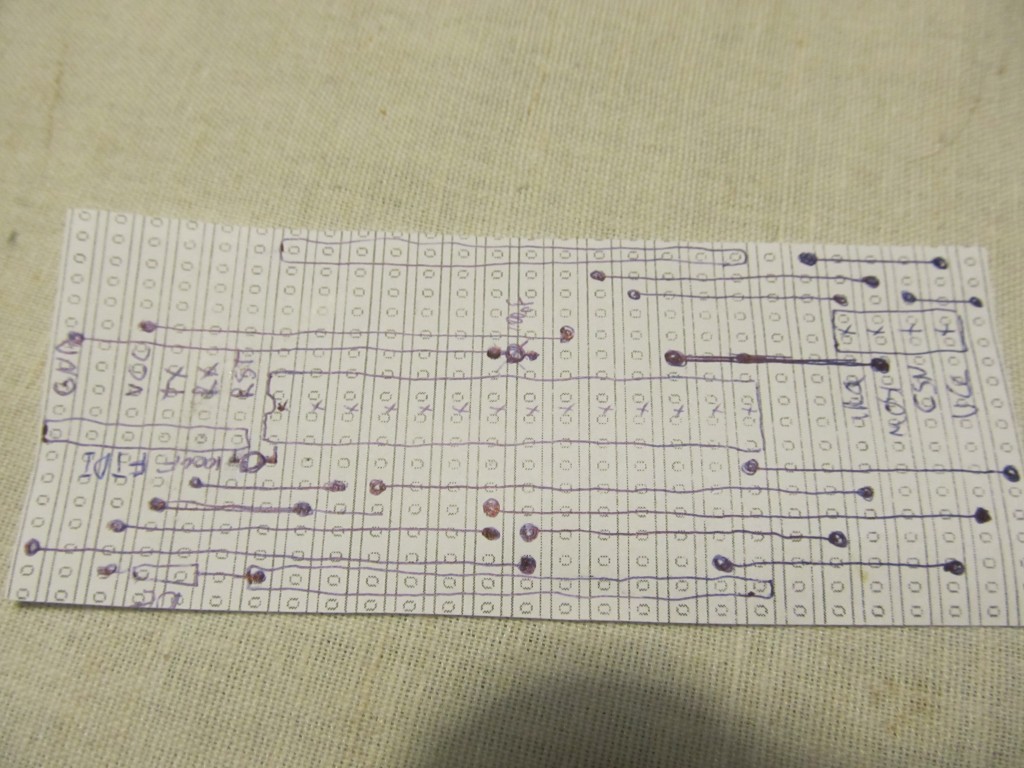
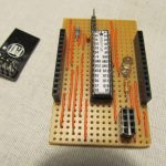
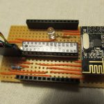
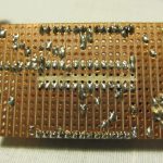
It is very basic indeed, I wanted FTDI pinout, headers to the side to plug sensors and a 4×2 header for the nRF24L01+ board. It will run on couple AA batteries (requires voltage anywhere from 3.3V down to 1.8V); Here is how it came along:

I only built one so far, so I figured I could try the “Poor man’s 2.4Ghz scanner” sketch to make sure all works. And it surely did:
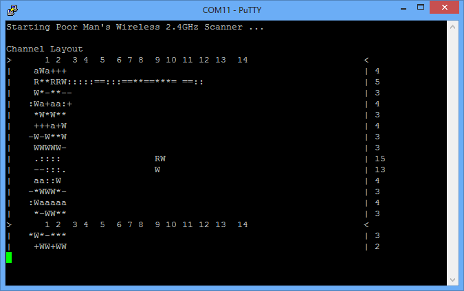
I changed my WiFi’s channel and the scanner immediately catches it. It also catches bluetooth and microwave oven interference. Useful to scan for free channels to use later when I have two of the nRF23L01+s talk to each other.
Next challenge is to find a decent library to use, there is at least 10 out there. I’d use one that supports interrupts to take advantage of low power features.
Thats a cool project idea. Do you plan to use the nRF24 modul as a replacement for the RFM12B? I also have a lot of RFM12B running in my sensor nodes.
Regards from Switzerland
Thomas
I think it would be wise to move away from the RFM12b now that it has been declared ‘end-of-life’, so these are my steps in that direction. I will see how it goes 🙂
There is already eagle files for something like this
Here
http://maniacbug.wordpress.com/2011/10/19/sensor-node/
As for library the manic bug one works with Pi / arduino and maple
http://www.raspberrypi.org/phpBB3/viewtopic.php?f=45&t=17061
I just wanted quick and cheap experiment, mine cost around 5-6 usd total to make
Pingback: nRF24L01+ range testing | Martin's corner on the web