
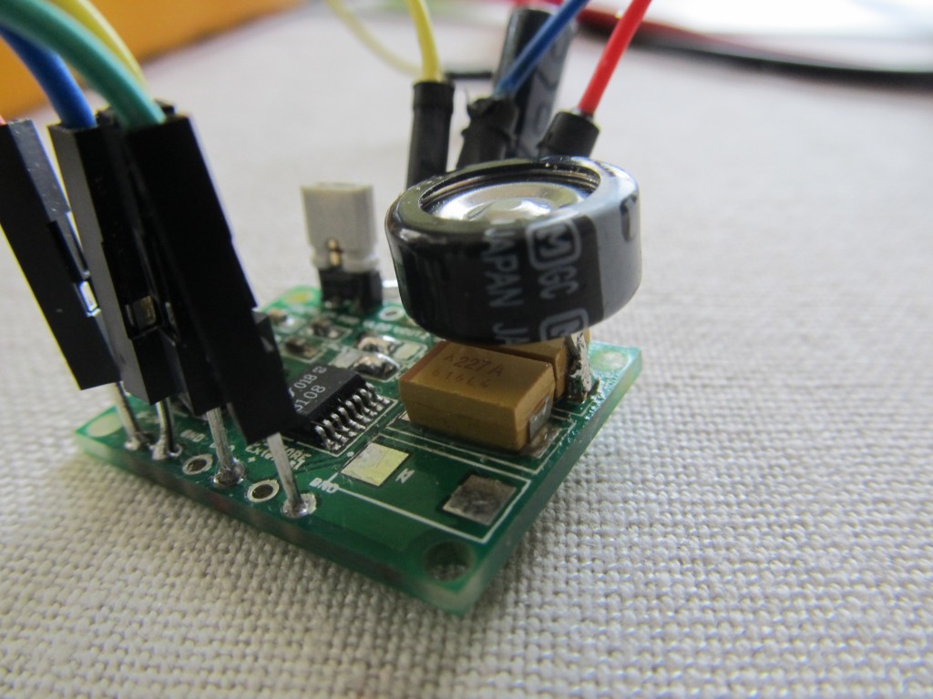
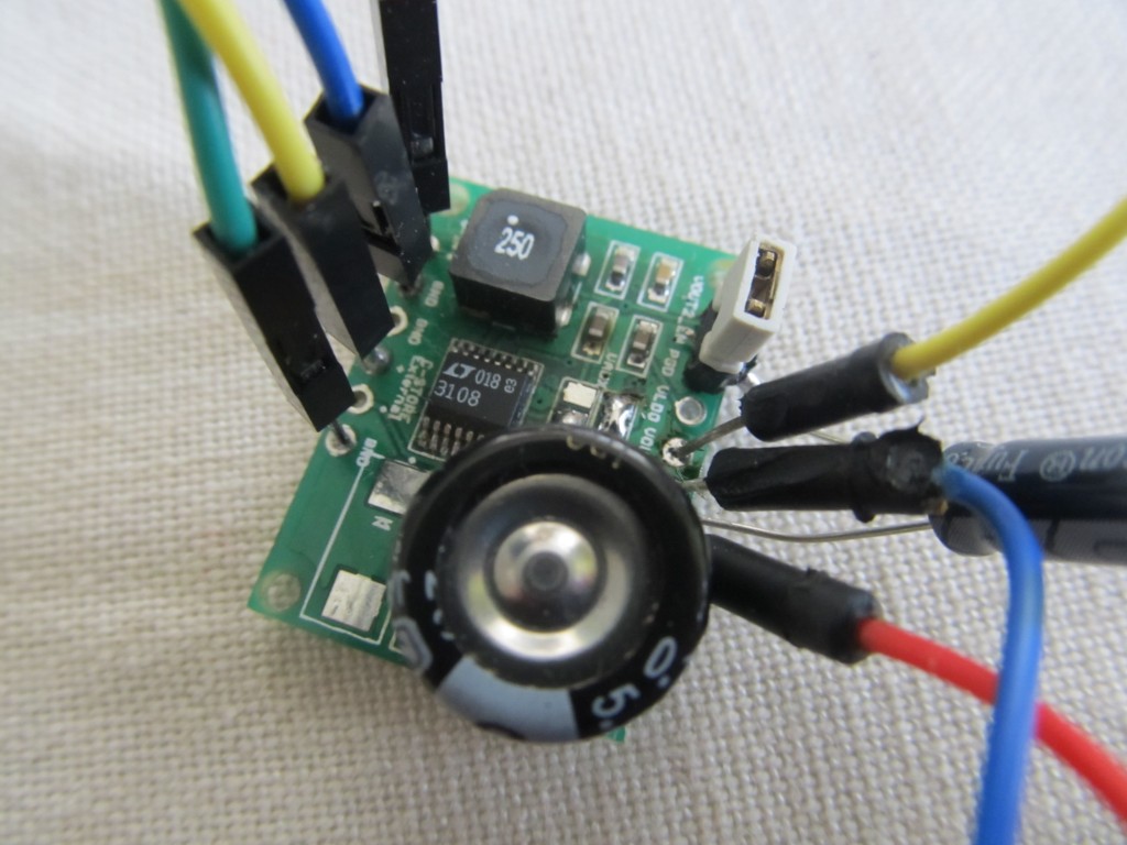
I have recently added a MOSFET to Funky v2 so it can control the power state of the RFM12B module. This was done in an attempt to allow starting up from a gradually rising power source, like the LTC3108 energy harvesting board would provide. All this was inspired by JCW’s work with the JeeNode Micro v3. As always, there seems to be discrepancy between expectations and the reality 🙂 The LTC3108 provides a very low charge trickle, in the range of 0.3mA for indoors light conditions, and a maximum of 4.5mA in ideal conditions. That means, that even though we can slowly charge the output capacitor to 3.3V with no load connected, once I have the Funky v2 attached things didn’t work as expected (now it all makes sense, but then I was puzzled). The problem is that there is a substantial current draw at the recovery from reset at around 1.4V, that draw exceeds the trickle charge and prevents the capacitor to further rise its voltage.. If I provide sufficient light, that hurdle is overcome, but the whole idea is broken. So I was upset, I can’t really use the MOSFET as I never get to startup. Yuck. Then I thought of something else: The LTC3108 has a Power Good output. Once VOUT has charged to within 7.5% of its regulated voltage, the PGD output will go high. If VOUT drops more than 9% from its regulated voltage, PGD will go low. But how can I use this? I figured that I could combine this with the other pin that is available: VOUT2_EN. Than pin enables the VOUT2 when brought high. So I connected PGD and VOUT2_EN, placed a 10uF electrolyte capacitor to the PGD and GND so it would keep the pin stable for a little while longer. Next, I added a 0.1F supercap on top the default COUT 470uF, that gives me a lot more time to operate and much more stable voltage.
So now I connected my Funky v2 to VOUT2 and GND and the LTC3108 starts it once the VOUT capacitor charges to slightly above 3.1V. The Funky then immediately powers down all unused peripherals and puts the RFM12B to sleep. The sketch will now have to wait for a full 3.3V before making heavy use of the transmitter. If the voltage falls below 3V, the whole thing is powered down and the cycle repeats.
So that works for me, I should have thought of it earlier.
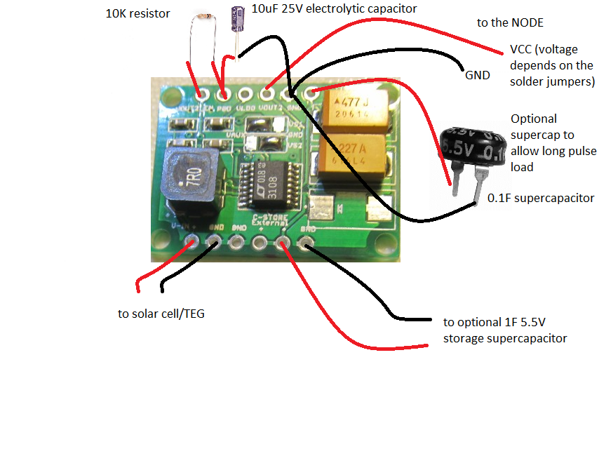
[EDIT May 21 2013]: I have adjusted my setup by adding a 10K resistor, it now works even better:
Hi Martin,
I stumbled upon your site from the Open Energy Monitor forums and found this post. I am not (yet) very knowledgeable in electronics development, so I hope you can answer my question:
Using this energy harvesting board, connected to a solar cell and a funky, would that mean the funky could be placed outside with (for example) a temperature sensor and send measurements to a RFM2PI, around the clock? In other words: is this board capable of storing enough power to get it through the dark hours, or would it require some additional power storage?
I am thinking about modifying a solar garden light to hide electronics inside and instead of lighting up at night, it continuously measures temperature, humidity and pressure and sends it periodically to a receiver inside.
This looks like it is small enough to store in there…
Yes, I tried that out. Using a 1F supercap it stayed up all night and was sending temperature readouts each minute, so it is a plug and forget type of solution.
If using a solar garden light, you may try to just use a boost converter and tap directly into the battery, I have such project blogged for Funky v1. Solar garden light’s cell is not suffucient to power the LTC3108