
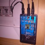
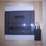
I have installed the first sensing shield on an Arduino Uno near my house’s breakers box. I finally got a 9V AC/AC transformer so I wanted to monitor my voltage, power factor and effective power usage in my house. I managed to squeeze in a power supply for the Arduino, the 9V AC/AC transformer and of course the CT inside the breaker box, but there was no room for the Arduino+Sensing shield so I placed them in a plastic Arduino enclosure.
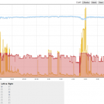
The sensing shield is sending the data to a NanodeRF and the NanodeRF is sending it to my emoncms installation. I use a multigraph to overlay these values. The voltage readings are a bit high, but they match my digital multimer as well. In my country it should be 220V, but readings are in the 240V range. Last year we got a new grid power transformer in our block, since then voltage has been higher.
The graph shows the expected small drop in voltage when powerful appliances are switched on. Power factor has been multiplied by 100 so that is visualizes on scale. It varies a lot, I will have to research further.
Pingback: Interfacing RFM12B to Raspberry Pi for cheap | Martin's corner on the web
Hi Martin,
Is it possible to run emontx and emoncms at one NanodeRF station?
So in other words to compile an arduino sketch for this 2 functions at one arduino setup. This because I have an ethernet cable at my breakers-box and don’t need an separate emontx at the house.
So it would be great to use 1 arduino for this 2 building blocks by using/buying your sensing shield!
Hi,
I assume by “emoncms” you mean the NanodeRF posting to emoncms installation that runs on a server elsewhere. The NanodeRF has a RFM12B that you will not use since you won’t have any remote sensors, right? You just need to read Voltage and Current and transmit to emoncms. This is easy task, as you say you can grab one of my shields and have only the voltage and one CT circuitry on it. You will need to get a current sensor (SCT-013-000) and a 9v AC-AC http://shop.openenergymonitor.com/ac-ac-adapter-euro-plug/wall adapter (sold out as I type this, hopefully they will restock).
The software side is pretty straight forward, just combine emontx code with emonBase code, removing RF stuff and using direct readings. Should be quite easy, if you don’t manage I may make such a example when I have extra time.
Yeah, I mean posting to emoncms. I have an linux ubuntu server running here at home for an other opensource project (zoneminder, cctv) so emoncms can run at this server. I also have the intention to use th RF chip later on for communication with some jeelabs nodes (nice dutch project 🙂 ) with temp DS18B12 sensors. But this is my first arduino project so my first attempt will be using the CT- and voltage- sensors on your sening board and an NanodeRF from the openenergymonitor shop.
I’m also learning C++ on the moment (I already now a lot of SQL because I’m an business intelligence consultant) so I will try to combine those TX and base sketches :).
Pingback: CR2032 powered “current only” remote monitoring | Martin's corner on the web
Pingback: Power supply block with ADCs for power monitoring | Martin's corner on the web
Pingback: Using my 1.8 TFT as a Raspberry Pi status display | Martin's corner on the web
Pingback: Martin's corner on the web
Pingback: Tweeting my house’s power usage as sparkblocks | Martin's corner on the web