
[This project is obsoleted and not supported]
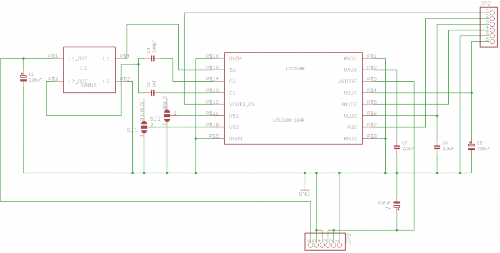
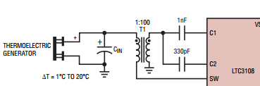
The LTC3108 is a highly integrated DC/DC converter ideal for harvesting and managing surplus energy from extremely low input voltage sources such as TEGs (thermoelectric generators), thermopiles and small solar cells. The step-up topology operates from input voltages as low as 20mV. Using a small step-up transformer, the LTC3108 provides a complete power management solution for wireless sensing and data acquisition. The 2.2V LDO powers an external microprocessor, while the main output is programmed to one of four fixed voltages to power a wireless transmitter or sensors. The power good indicator signals that the main output voltage is within regulation. A second output can be enabled by the host. A storage capacitor provides power when the input voltage source is unavailable. Extremely low quiescent current and high efficiency design ensure the fastest possible charge times of the output reservoir capacitor.
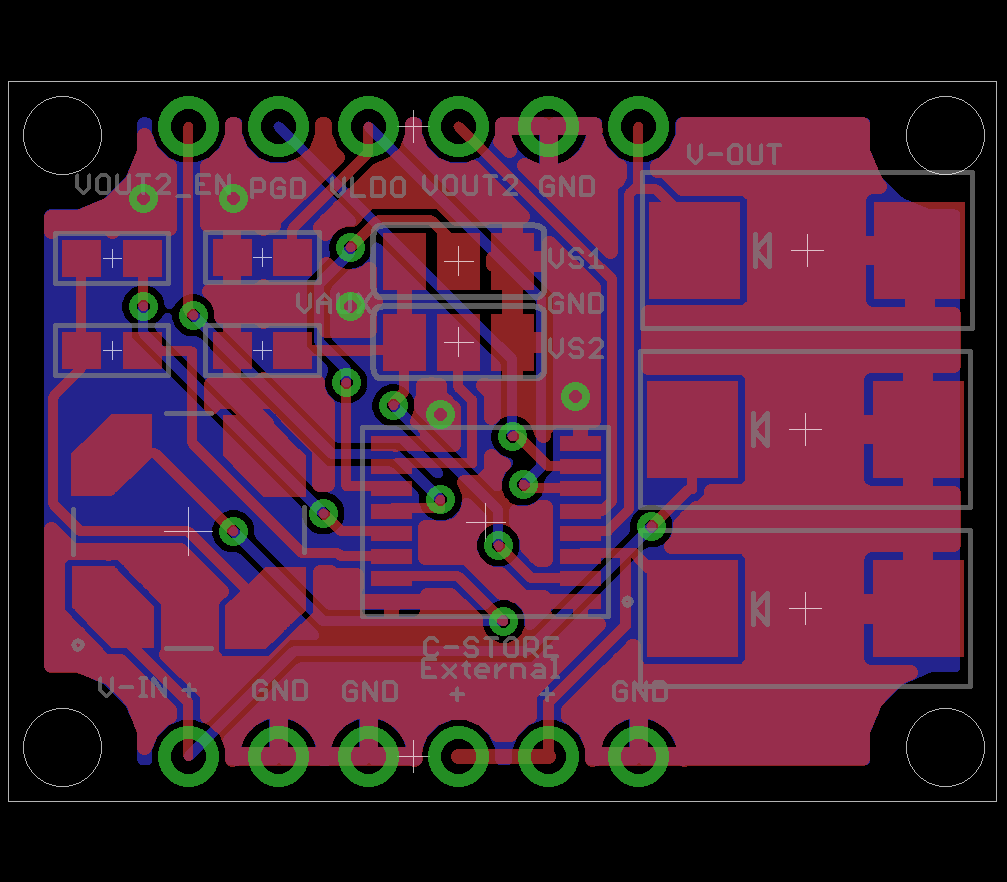
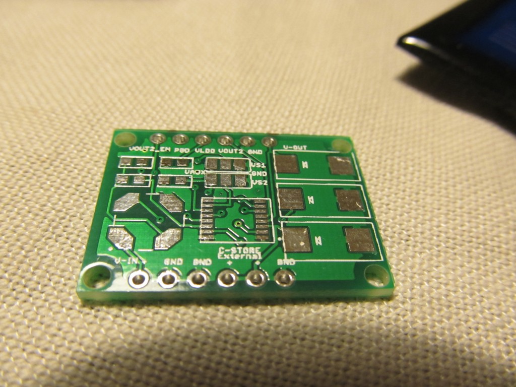
Selecting the VOUT voltage is done by connecting the two solder jumpers on the board as follows:
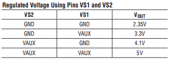
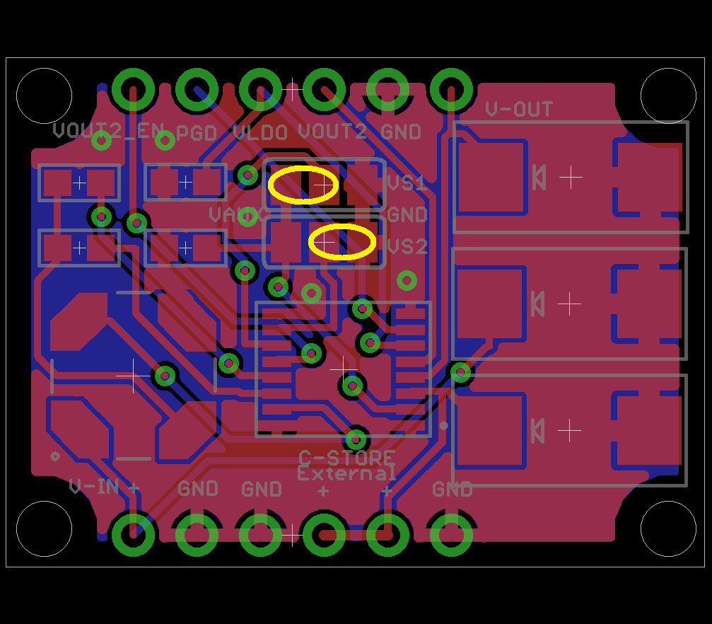
For example to chose 3.3V for VOUT, the solder jumpers must be configured as shown:
Primary application of the breakout board would be to provide power for small pulsed load applications, i.e. remote sensors that will periodically wake up, make a measurement and transmission and then go in sleep mode to allow sufficient amount of energy to be accumulated for the next pulse. The VOUT capacitor should be sized to provide the necessary current when the load is pulsed on. The capacitor value required will be dictated by the load current, the duration of the load pulse, and the amount of voltage drop the circuit can tolerate. The capacitor must be rated for whatever voltage has been selected for VOUT by VS1 and VS2.
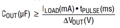
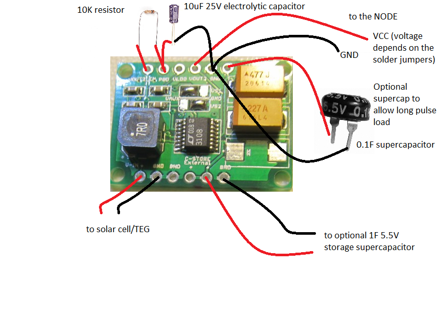
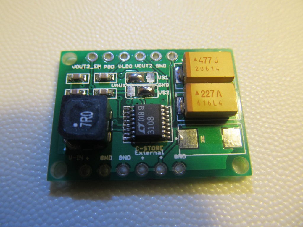
A remote node (Funky, JeeNode etc low power nodes) that utilizes a RFM12B transmitter typically makes a transmission for 5ms and uses 25mA. We can afford to drop the voltage from 3.3V to 3V (or even 2.7V) or delta VOUT=0.3V. The minimum value for COUT capacitor then calculates to 416uF or the closest standard 470uF value can be used. Of course, by assuming the voltage drop to 0.5V (perfectly acceptable for Funky and JeeNode) a smaller COUT value can be used. To be on the “safe” side, I will use 470uF tantalum capacitors for COUT. You can solder additional capacitor in addition to the on-board one to increase the pulse time. I have experimented with soldering a 0.1F supercap on top the 470uF capacitor and achieved great results.
Note that there must be enough energy available from the input voltage source for VOUT to recharge the capacitor during the interval between load pulses. Reducing the duty cycle of the load pulse will allow operation with less input energy.
CIN capacitor is fixed to 220uF as recommended in the datasheet.
The board has a footprint for a third SMD tantalum capacitor for VSTORE, but that is optional to solder. In the majority of cases, a super capacitor rated at least 5.5V would be a more appropriate storage for the excess energy. In my tests I used a 1F super capacitor. The Storage capacitor will provide power to the system in case the input voltage is lost, i.e. at nights if using a solar cell. Using storage capacitor may not be necessary, if running on TEG as these provide constant input power.
VLDO is the output of the 2.2V LDO; It is intended to power a MCU that will monitor the Power Good (PGD) pin and enable (by setting VOUT2_EN to high) the VOUT2 that in its turn will power an external RF module.
There will be two build options: one for Peltier cell and another for Solar cell. The difference is as per the datasheet recommendations:
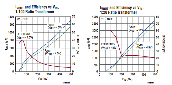
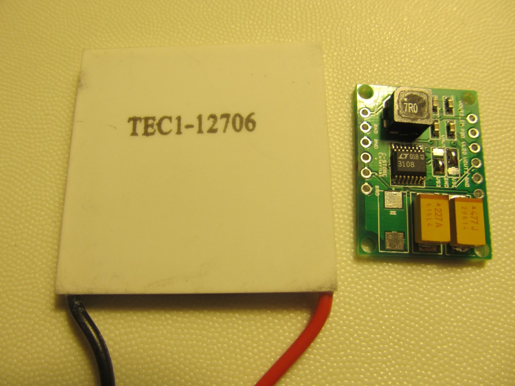
Build A) “Peltier cell” build will have 1:100 ratio transformer, 1nF value for C1
I have used this ebay seller’s Peltier element and achieved excellent results
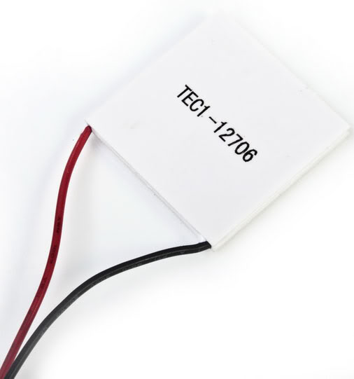
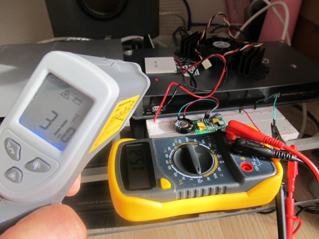
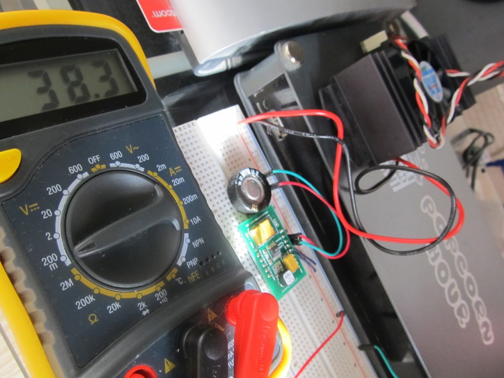
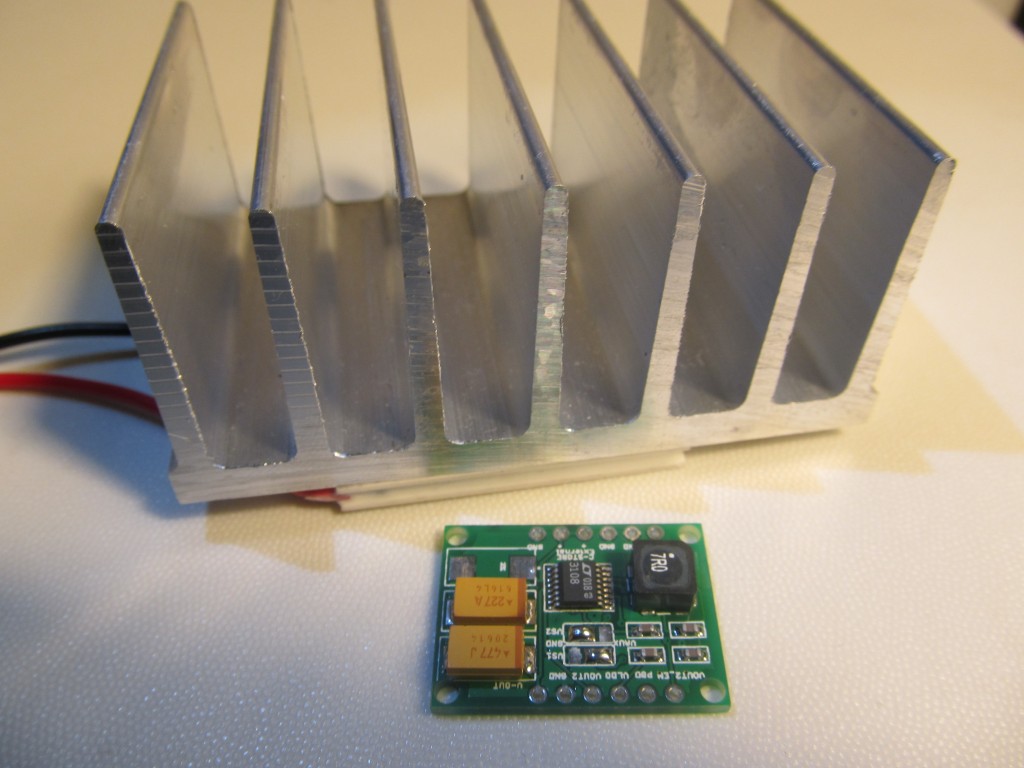
When using with a Peltier element, you need to find a surface where temperature difference can be utilized. I have IR thermometer that I used to look for such places around my house, no surprise to find that the best sources of heat are power supplies. I have a home entertainment network media center that is around 30-35 degrees C at its surface and by placing the Peltier on top of it with an aluminium heat sink, I get excellent results. Note that you don’t necessary need heat, what you need is temperature difference between the two plates of the element. I tested inside a fridge where the temperature on the wall where the coolant flows is -20 degrees C and the inside of the fridge is +5 degrees C; That creates excellent power output too.
This build starts up at 20mV input and is optimized for use with a Peltier element. It will work with a solar cell too, but at the cost of decreased efficiency i.e. slower recovery time, but it will start up at much lower light level, so it is a balance decision.
Build B) “Solar cell” build will have 1:20 ratio transformer, 0.01uF for C1
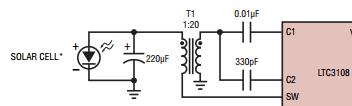
The LTC3108 converter can also operate from a single photovoltaic cell (also known as a PV or solar cell) at light levels too low for other low input voltage boost converters to operate. However, many variables will affect the performance in these applications. Light levels can vary over several orders of magnitude and depend on lighting conditions (the type of lighting and indoor versus outdoor). Different types of light (sunlight, incandescent,
fluorescent) also have different color spectra, and will produce different output power levels depending on which type of photovoltaic cell is being used (monocrystalline,
polycrystalline or thin-film). Therefore, the photovoltaic cell must be chosen for the type and amount of light available. Note that the short-circuit output current from the
cell must be at least a few milliamps in order to power the LTC3108 converter.
This build starts up at 100mV input and 3-4mA current.
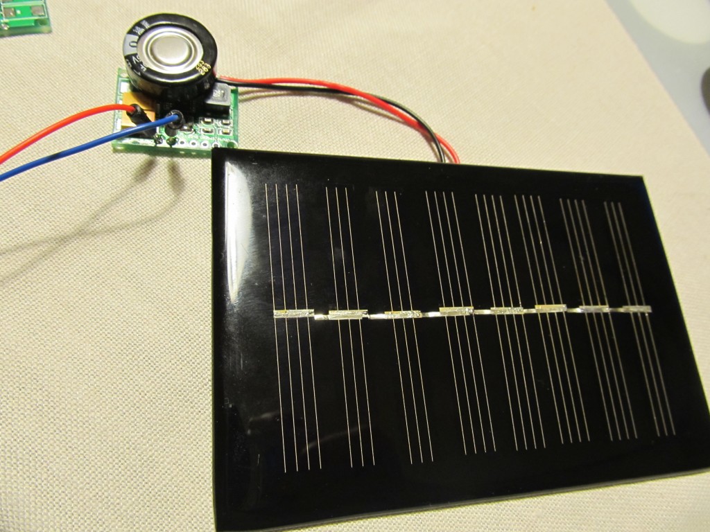
I haven’t tested this particular model, but these cells look excellent for the purpose.
See this post for usage with Power Good pin enabling VOUT2. To use this setup, connect the board as follows:
The advantage of the above setup is that it will only power up the attached node when voltage reaches the pre-set with jumpers level and will power off once it drops below.
See a demo video:
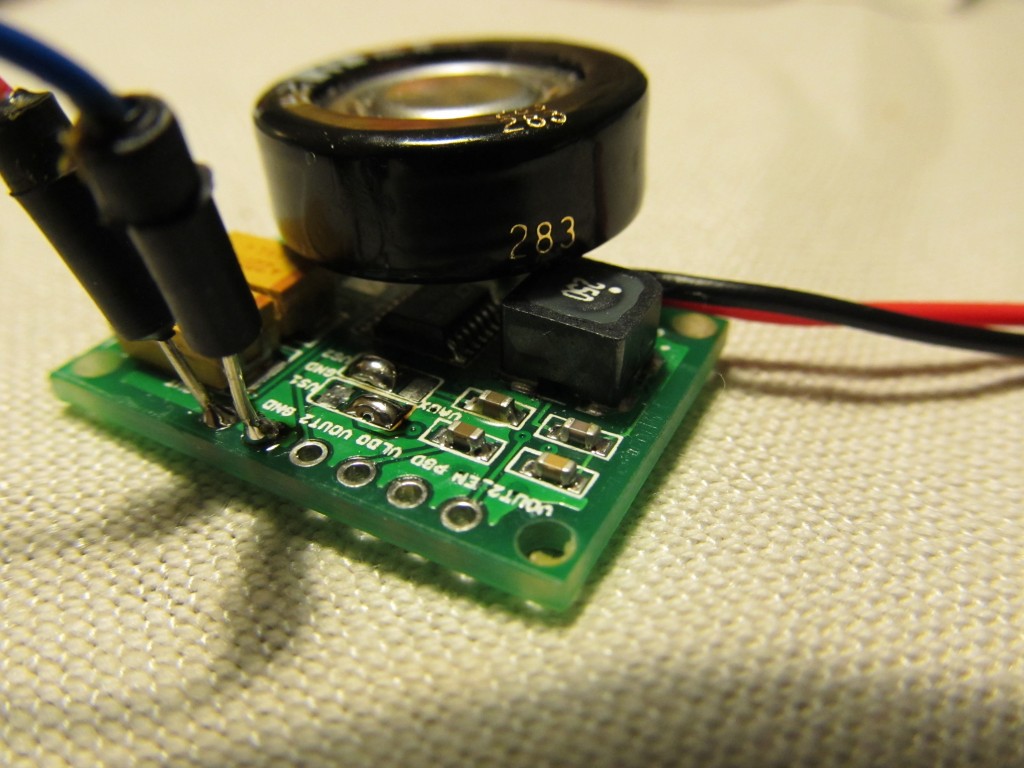
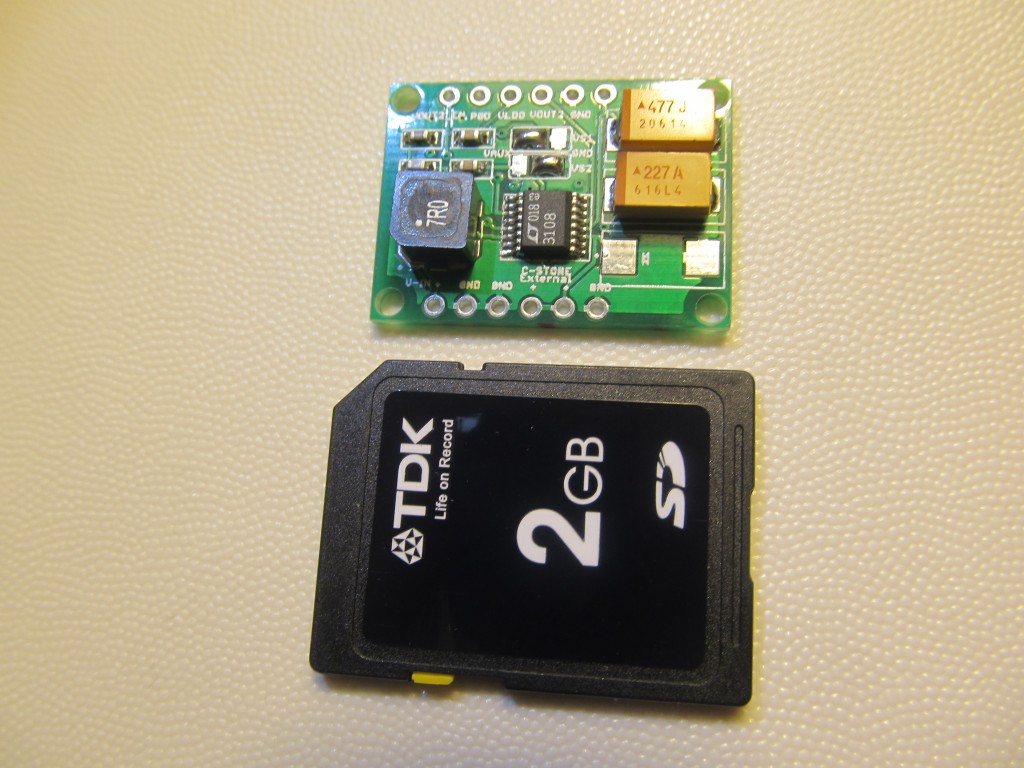
Some pictures:

sir.. ur board circuit made by urself or u buy it? how get i get 1 of those?
Hello,
http://harizanov.com/product/ltc3108-breakout-board-for-energy-harvesting/
could i request for a custom circuit which is singler layer circuit?
sir.. the package for LTC3108 IC u use is in DFN or SSOP?
hello sir,
I just want to ask, if I buy your circuit does it comes with all the components on it?
or just the plain circuit
thanks.
Hello,
it comes fully populated with all components on-board.
hello,
I want to ask about the cost of shipping..is it a flat rate for all country
and how long it takes for the duration of delivery
thanks
Yes, flat fee of 3 EUR for shipping worldwide. It may be slow, if you live outside Europe, up to 30 days to reach you. I can use EMS, but that is much more expensive.
I wanted to ask you a question.
I am interested in the TEG connected circuit (trans 1:100)
What is the efficiency of this device ?
How do you measure it?
The datasheet elaborates on the efficiency, it is not linear and varies a lot according to the input parameters: http://cds.linear.com/docs/en/datasheet/3108fc.pdf
I’m not sure how they measured it, but should be reliable.
Hey, would you share the board files or gerbers with me? I just want to make a one-off, nothing commercial.
Hi, I buy these; Check http://www.electrodragon.com/product/esp8266-wifi-board-full-ios-smd/
What has that got to do with a LTC3108 breakout?
I found this which is really what I was looking for: https://github.com/wa7iut/LTC3108-Breakout-SSOP