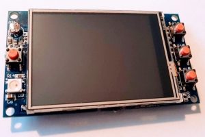
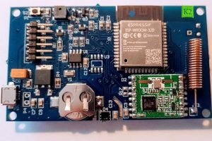
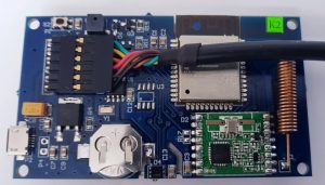
DS1338 real-time clock with battery backup (CR1220 battery not included)
Four multi-purpose buttons
Option for ATSHA204 crypto authentication device (not included)
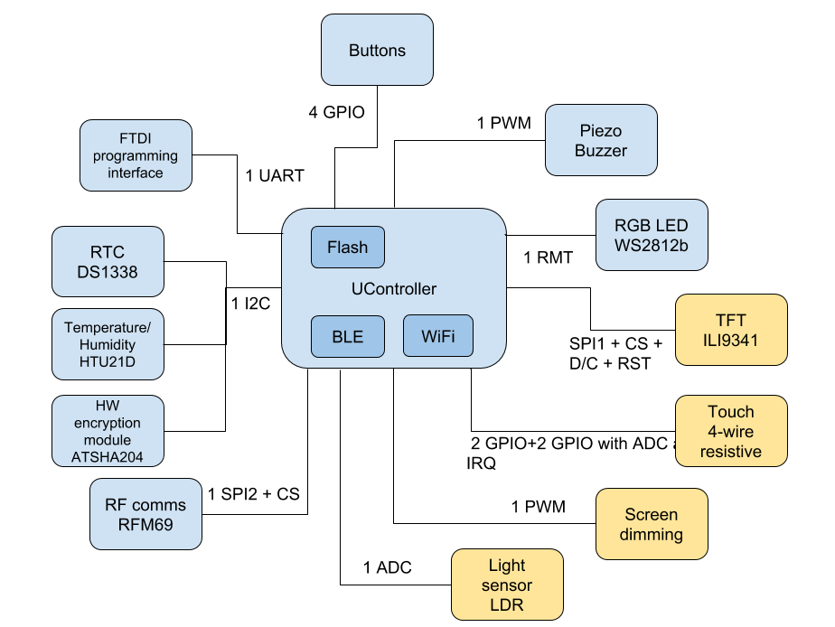
Logical peripherals diagram
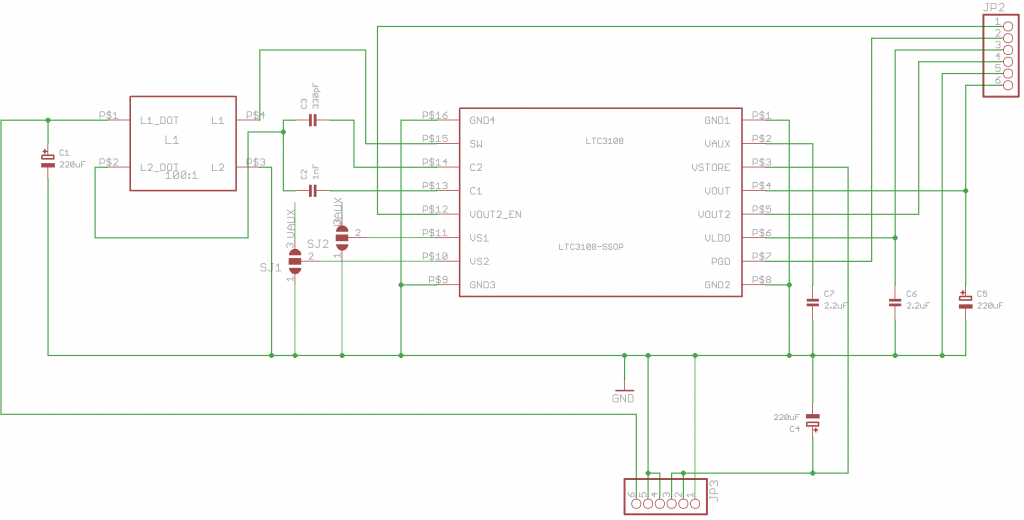
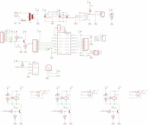
Schematic
Powering it
The TFT32 can be powered from the micro USB port or the FTDI programming socket (P1). Alternatively, the board can be powered from 12-6V source using the auxiliary power connector (P4).
Programming it
The micro-USB port is only used to provide power, not for programming the TFT32. The TFT32 is programmed using FTDI programming socked located on the back of the product. To program the TFT, please use 3.3V logic level FTDI programmer that can supply at least 500mA current.
FTDI connector
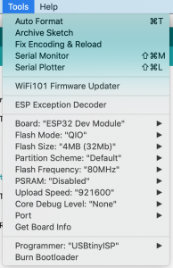
Arduino settings
Note: In order to flash the TFT32 with new firmware, you need to press and hold button 1 (marked with S1 on the silk, connected to GPIO 0) for a short time as the firmware upload starts
I highly recommend using LittlevGL for GUI development on the TFT32.
LittlevGL is a free and open-source graphics library providing everything you need to create embedded GUI with easy-to-use graphical elements, beautiful visual effects, and low memory footprint.
Example Arduino source code for touchscreen Christmas lights controller with MQTT backend is available to get you started with LittlevGL and the TFT32 on my Github repo.
Christmas lights controller
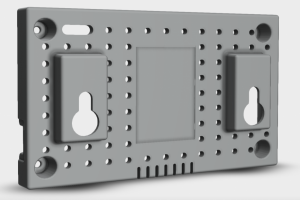
3D printable enclosure
A 3D printable enclosure is available for free here.
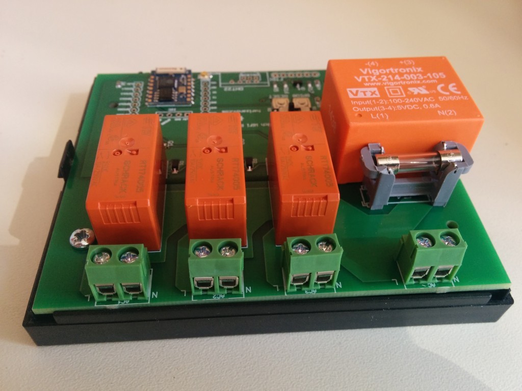
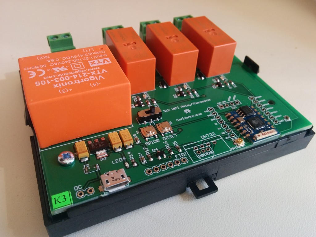
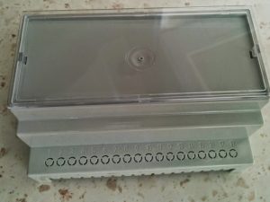
The Three Channel WiFi Relay / Thermostat Board is a open software/hardware multi-purpose relay board based on the ESP8266 WiFi SoC. It can control up to three AC or DC loads over the Internet using web UI or MQTT.
NOTE: The board connects to and controls high voltage, knowledge and attention is required when installing it. It is recommended to use the compatible enclosure to prevent electrical shock.
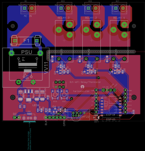
Board schematic & layout
Three Channel WiFi Relay/Thermostat Board schematic and board layout files are available on GitHub
Board Schematic
Board Layout Design
The PCB is 2mm thick with 35 micron foil.
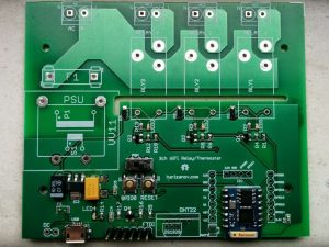
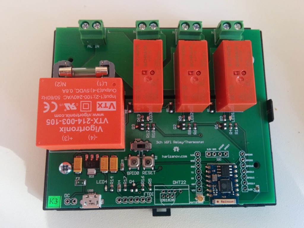
Relay board less relays PSU, PSU fuse and screw terminals
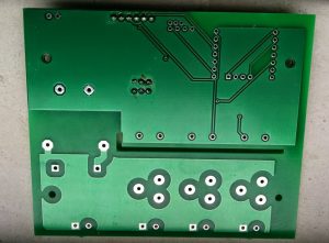
Relay board less relays PSU, PSU fuse and screw terminals – bottom
Firmware
The latest firmware is available on Github. Firmware can be update using a *3.3V* FTDI cable, check the dedicated section of this WIKI.
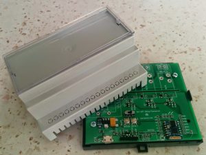
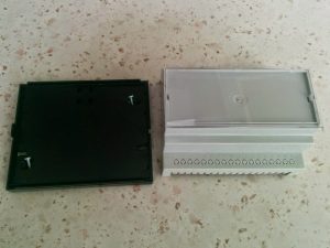
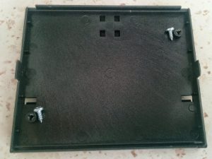
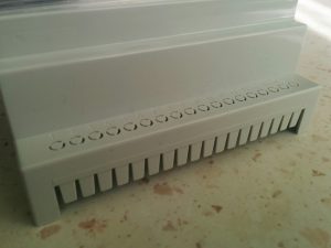
Enclosure
The PCB is designed to fit in a high quality DIN rail-friendly enclosure. It is highly recommend to use the enclosure to protect yourself from electrical shock. Knock-out entries on the side lid allow custom configuration on the outputs:
Via the DC power terminal next to the USB plug (7-10V DC)
Via the FTDI header using a 3.3V Logic Level FTDI cable (it still supplies 5V to the power pin)
Mind the live and neutral markings on the board, make sure Live wire connects to the L side of the screw terminal:
NOTE:
When connected to AC, handle the board with extreme care. Bottom and top of the high side of the board will be live and accidental touch may result in injury or death.
Connecting AC loads
Loads can be connected to the screw terminals next to the relays, please mind connecting Live and Neutral lines respectively.
NOTE: The relays are rated 10A, however I’d rather not utilize all three of them at maximum load, as that would cause 30A current to flow through the source AC screw terminal
Connecting DC loads
The board can be used for DC load switching, if the power supply unit is not populated on the board. Power the board from the USB connector or DC input.
Connect positive to the L and negative to the N side of the screw terminal.
Configuring the board
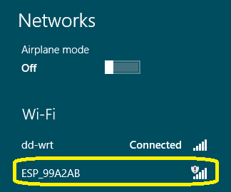
The board’s parameters are configured through web UI. Upon first boot, the board will enter Access Point mode and you will be able to see it as such by scanning the WiFi networks.
The Access Point name would start with “ESP_” followed by the access point MAC address. There will be no security or password. The access point will be switched off after a successful connection to the wireless network.
If the board does not show up, you may manually force the board into AP mode by pressing and holding the button labeled “GPIO0” for 3 seconds and then releasing it. NOTE: Mind the high voltage side of the board while doing so!!
Once connected to the access point, navigate your browser to http://192.168.4.1, if all worked well, this should take you to the main menu. Please note that some mobile phones will detect that the WiFi connection does not provide Internet and fall back to GSM data network. Make sure to disable mobile data so that your browser still uses that access point.
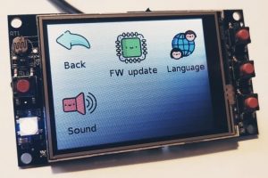
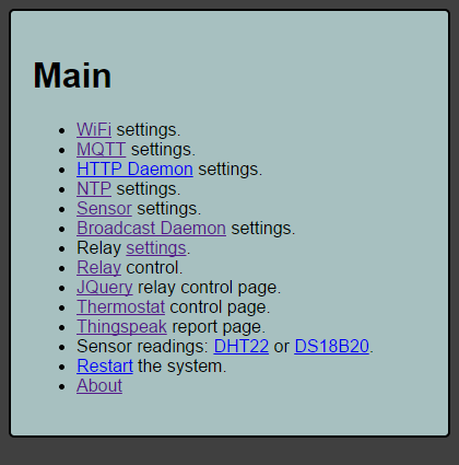
Main Menu
The main menu provides links to the respective sub-menus
WiFi connection setup
The WiFi connection menu lets you connect to your WiFi network. It will scan for the available networks and prompt you to chose it. Select the network, type in the network key and choose whether to use dynamic IP through DHCP or static IP address. Using static IP address makes most sense, as you would be able to access the board by its known IP address.
You will need to set up port forwarding if you wish to access the relay board from outside the network.
I use the following linux command to find the IP address of the ESP8266 modules connected to my network:
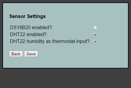
Sensor settings menu allows you to enable one of the two possible sensor daemons, DS18B20 or DHT22 (not both at the same time).
Multiple DS18B20 temperature sensors may be attached, thermostat function will use the one with smallest address.
The humidistat function can be enabled by choosing the humidity readout of DHT22 as input to the thermostat.
Temperature/humidity is checked every 30 seconds (hardcoded).
NOTE: Soldering the sensors directly on the board is not recommended as the PSU and the ESP8266 disperse heat and if the sensor is soldered on the PCB directly, there will be heat transfer and falsely high readings. For best results use wires and have the sensor outside the enclosure.
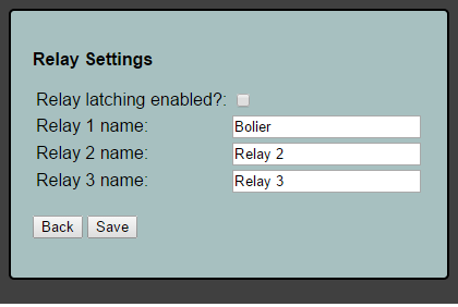
Relay Settings
This menu allows you to put a custom name to the relays e.g. “Boiler”, “TRV” etc
Second function is to implement relay “latching” i.e. preserve last relay state upon restarting/power loss recovery.
NOTE: Be careful with the function as it may energize the relay upon starting up the board if its last state was ON.
Relay 1 name is used as zone name in the thermostat control page.
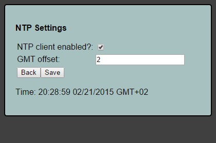
NTP settings
Network Time Protocol settings enable the NTP function; Must be enabled when using the thermostat scheduler function so that the relay knows the current date and time and act upon the schedule accordingly. NTP provides GMT time, add negative or positive offset accordingly.
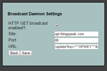
Broadcast settings
This function allows the board to “broadcast” its basic state via HTTP GET.
As example, the URL for thingspeak posting is formatted as follows:
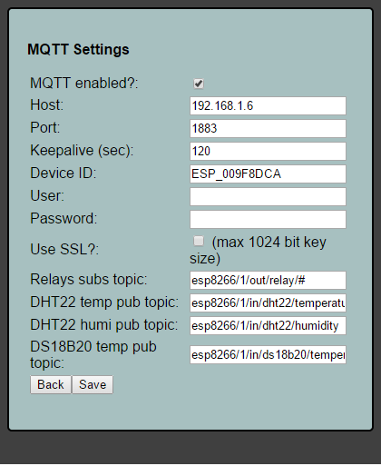
MQTT settings allows enabling and configuring MQTT for the board. The board can subscribe itself to MQTT topic and control the relays from that topic. It will publish temperature and humidity (DHT22) data to respective topics as well.
NOTE: SSL does not currently work due to heap size issues when enabled.
Example of using mosquitto_pub to turn the relays on/off
mosquitto_pub -d -t esp_009F8B46/out/relay/1 -m 1
mosquitto_pub -d -t esp_009F8B46/out/relay/1 -m 0
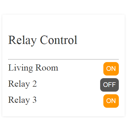
Relay control UI
The relays can be controlled via a simple mobile device friendly UI. Just click on the On/Off button to change their state. Relay names are set via the Relay Settings menu.
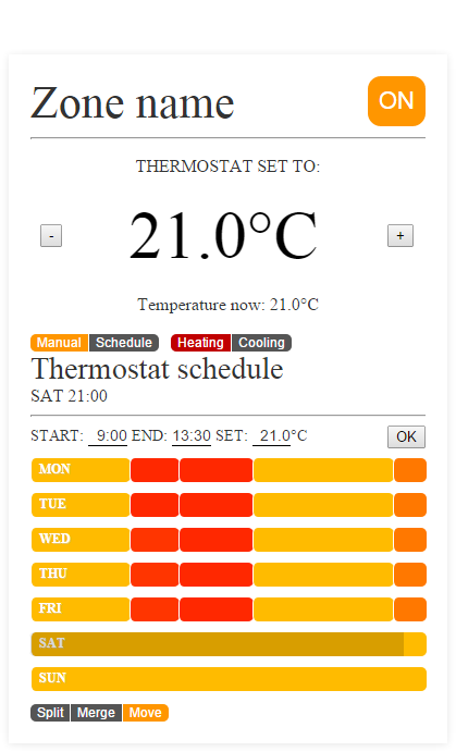
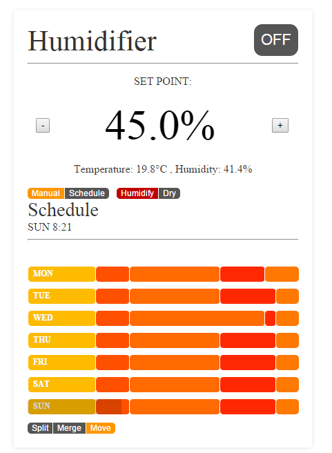
Thermostat/Humidistat function
Thermostat function allows setting manual setpoint or using weekly schedule. NTP time must be enabled when using schedule. Thermostat code only controls relay №1.
The schedule is adjusted by moving the slides to the left or right, these represent schedule blocks on a 24 hour scale. Block boundaries can be moved, blocks can be merged or split into more detailed schedule blocks. Each block has setpoint, color represents the setpoint value (yellow-orangish-red).
Thermostat will not function until it is in “ON” state. Manually setting the setpoint will switch to “Manual” mode. Switching off the thermostat function will force off relay 1.
Cooling mode will invert relay logic, I plan to use that for controlling fan coils in cooling mode during the summer.
Setpoint changes color to RED when relay 1 is activated and black when relay 1 is off.
Humidifier function, enabled via the ‘Sensor settings’ menu:
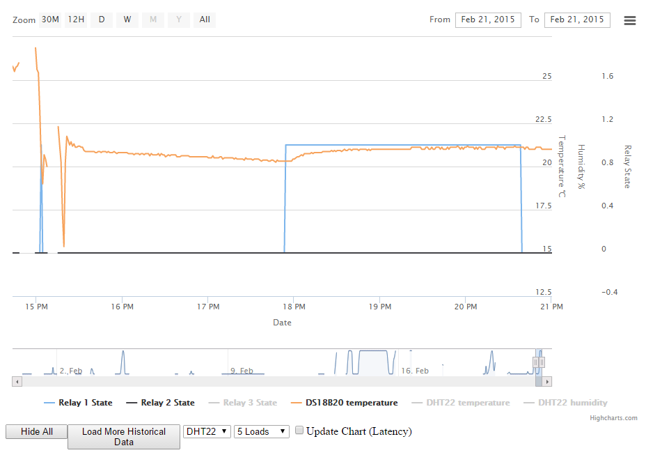
Thingspeak report integration
If broadcasting to thingspeak, a report that is using JavaScript to fetch data from thingspeak and render it is available
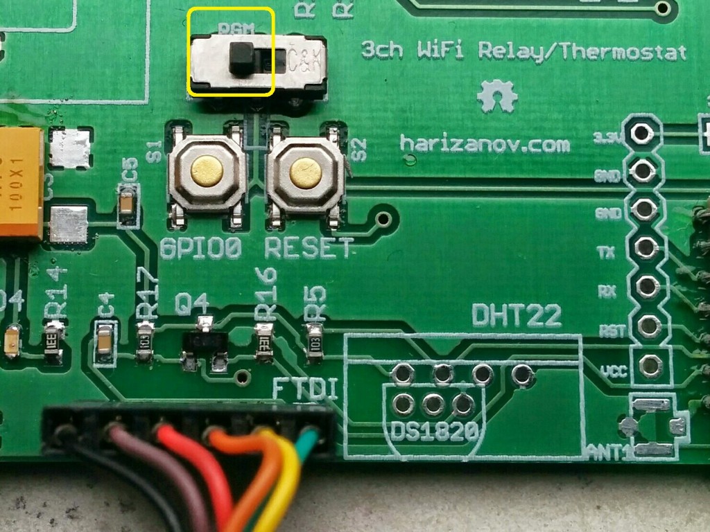
Firmware update
To change firmware, set the programming switch to “PGM” position and attach *3.3V* FTDI cable with GND (black wire) towards the USB plug:
The above HTTP request will switch relays 1 and 3 ON and set relay 2 to OFF. If security was enabled, you will need to provide means for HTTP Basic authentication.
The current relay states can be retrieved using the following request
http://RELAYADDRESS/control/relay.cgi?state
This returns a JSON string with the current relay states and their names (set via the UI):
No need for external programmer to upload new sketch – just use micro USB cable
Equipped with 433/868 wireless RFM12B or RFM69CW transceiver module
Runs on 8 Mhz and can be powered from 2.7-3.3V power source, including coin cell battery
Low power operating mode
Board schematic & layout
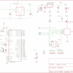
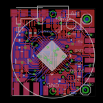
Funky v3 schematic and board layout files are available on GitHub
Funky v3 schematic
Funky v3 board layout
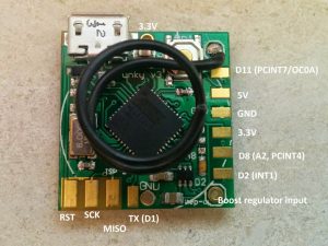
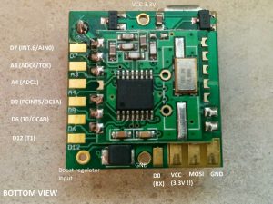
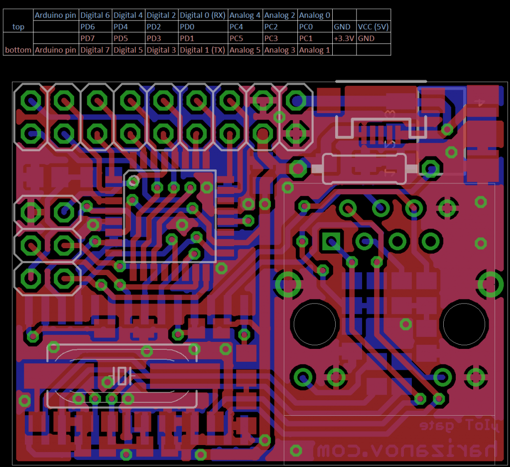
Pins legend
Pins mapping:
Top view
Bottom View
Powering it up
Via the USB
Simply plug in the Funky to micro USB cable and it will be powered up.
NOTE: Please remove any battery attached when plugging into USB.
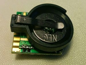
Coin cell (CR2032)
Coin cell holder can be directly soldered on the bottom of Funky v3
Optional coin cell holder CR2032, not included
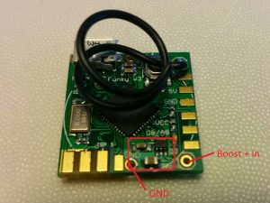
If you wish to use CR2032 battery in combination with the optional LTC3525 boost regulator, you will need to bend the positive pin and route that with a wire to the boost regulator entry.
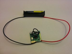
AA(A) Batteries
Use two AA(A) batteries on the VCC and GND to supply 3V to the Funky v3
Use 3 AA(A) batteries connected to the 5V and GND to supply 4.5V to the on-board LDO that will regulate it to 3.3V
Boost Regulator
The board carries an option for the LTC3525ESC6 (3.3V version) boost regulator and supporting elements to be included, this is useful when you wish to power the board from a 0.8 – 5.5V source and get that regulated to 3.3V.
The LTC3525 and supporting passive components. Note the boost regulator entry
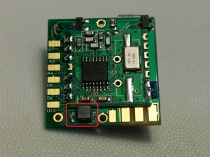
The boost regulator inductor
Powering the Funky v3 from single AAA battery
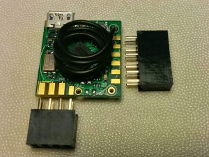
Side Headers
Funky v3 can be powered from the side headers (3.3V and 5V possible)
If your project requires it, you may solder 6×2 headers to the side pins and another 4×2 on the bottom pins as shown below
Optional side headers (not included)
The header pins will require slight filing to shorten the metal pins length for best fit
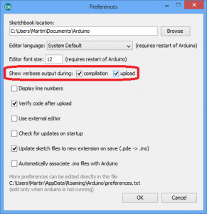
Arduino IDE
Setting up
Download and install the latest Arduino IDE from the official Arduino site. Setting it up is straight forward.
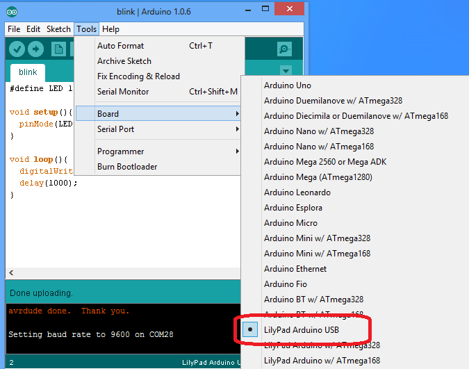
Chose the board type
Select “LilyPad Arduino USB” as board type, it uses the same MCU/Clock speed as the Funky v3, so I have decided to use that as board type rather than own custom board type that would require more difficult user setup:
Click to enlarge
Libraries
Using the RFM12B/RFM69CW transceiver will require that you install the Jeelib library
Using the RFM69CW radio module instead of the RFM12B is possible, just make sure you include the following define:
#define RF69_COMPAT 1 // define this to use the RF69 driver i.s.o. RF12
The RFM69CW module must be initialized as soon as possible in the sketch as until initialized, it is quite power-hungry and will brown-out the Funky v3 after a short while. A 10uF 0805 SMD ceramic capacitor must be soldered on the boost regulator circuitry to support the RFM69CW module. It also uses double the transmission power to that of a RFM12B (45mA compared to 23mA), so may be less suitable for low-power operation mode.
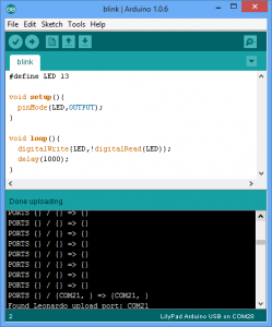
Uploading new sketch
Just hit the ‘Upload’ button in Arduino IDE.
If for some reason the sketch won’t upload, hit the ‘Reset’ button on the Funky v3 just when the IDE starts looking for the board, this is easily identifiable by the text “PORTS {} / {} => {}” in the debug window as pictured below:
The module comes with bootloader and the RF12Demo sketch installed, so you may start toying immediately.
Blinky example
Grab the Blink example from GitHub and upload to the board. The on-board LED should blink every second
LED is connected to pin digital 13
Using the RFM12B/RFM69CW
Prerequisite: the Jeelib Arduino library, see the above “Library” section
Powering up the module
The RFM12B module must be explicitly powered up by writing LOW to Digital 4. Make sure to power up the module *before* any attempt to initialize it, otherwise it will simply fail.
 pinMode(4,OUTPUT); // Funky v3 RFM12B power control pin
 digitalWrite(4,LOW); //Make sure the RFM12B is on, yes LOW is ON
 delay(100); // Delay (or sleep) to allow the RFM12B to start up
Initializing the radio module
The following code will initialize the RFM module to NodeID=22, 868Mhz and network group of 210
rf12_initialize(22,RF12_868MHZ,210);
rf12_control(0xC000); // Adjust low battery voltage to 2.2V, only for RFM12B
rf12_sleep(0);  // Put the RF module to sleep
Send example
The following code will send a payload structure over the radio link
typedef struct {
	  int temp;	// some structure as payload
} Payload;
Payload temptx;

rf12_sleep(-1);  // Wake up RF module
while (!rf12_canSend())
            rf12_recvDone();
rf12_sendStart(0, &temptx, sizeof temptx);
rf12_sendWait(2);  // Wait for RF to finish sending while in standby mode
Low power
Running on batteries requires special care to cut power consumption to its lowes possible. This is possible by both hardware architecture and software code.
Detecting USB
It makes sense to keep USB connectivity ON when we are powered by the USB and not running on battery power. That enables us to use serial debugging/configuration of the module. To identify if we are running on battery or plugged into USB, use the following code:
 USBCON = USBCON | B00010000;

 delay(550); // Necessary, some systems may even require longer delay

 if (UDINT & B00000001){
 // USB Disconnected; We are running on battery so we must save power
 }
 else {
// Running on USB power, we can be wasteful
 }
The following code will reduce power usage to maximum possible extend by switching off certain peripherals and switching to the internal RC rather than the external crystal. This will allow the Funky v3 to run longer on battery.The code will disable USB connectivity, so you will need to hit the ‘Reset’ button to upload a new sketch:
 ADCSRA =0;
 power_adc_disable();
 ACSR |= (1 << ACD); // disable Analog comparator, saves 4 uA
 power_usart0_disable();
 //power_spi_disable(); /do that a bit later, after we power RFM12b down
 power_twi_disable();
 power_timer0_disable(); // Do not disable if you need millis()!!!
 power_timer1_disable();
 power_timer3_disable();
 PRR1 |= (uint8_t)(1 << 4); //PRTIM4
 power_usart1_disable();
 // Switch to RC Clock
 UDINT &= ~(1 << SUSPI); // UDINT.SUSPI = 0; Usb_ack_suspend
 USBCON |= ( 1 <<FRZCLK); // USBCON.FRZCLK = 1; Usb_freeze_clock
 PLLCSR &= ~(1 << PLLE); // PLLCSR.PLLE = 0; Disable_pll
 CLKSEL0 |= (1 << RCE); // CLKSEL0.RCE = 1; Enable_RC_clock()
 while ( (CLKSTA & (1 << RCON)) == 0){} // while (CLKSTA.RCON != 1); while (!RC_clock_ready())
 CLKSEL0 &= ~(1 << CLKS); // CLKSEL0.CLKS = 0; Select_RC_clock()
 CLKSEL0 &= ~(1 << EXTE); // CLKSEL0.EXTE = 0; Disable_external_clock

 // Datasheet says that to power off the USB interface we have to:
 // Detach USB interface
 // Disable USB interface
 // Disable PLL
 // Disable USB pad regulator

 // Disable the USB interface
 USBCON &= ~(1 << USBE);

 // Disable the VBUS transition enable bit
 USBCON &= ~(1 << VBUSTE);

 // Disable the VUSB pad
 USBCON &= ~(1 << OTGPADE);

 // Freeze the USB clock
 USBCON &= ~(1 << FRZCLK);

 // Disable USB pad regulator
 UHWCON &= ~(1 << UVREGE);

 // Clear the IVBUS Transition Interrupt flag
 USBINT &= ~(1 << VBUSTI);

 // Physically detact USB (by disconnecting internal pull-ups on D+ and D-)
 UDCON |= (1 << DETACH);

 power_usb_disable(); // Keep it here, after the USB power down

 // Initialize and put the RFM12B to sleep, make sure it is powered before attempting to talk to it..
 rf12_initialize(storage.myNodeID,storage.freq,storage.network,1600); // Initialize RFM12
 // Adjust low battery voltage to 2.2V
 rf12_control(0xC000);
 rf12_sleep(0);                          // Put the RFM12 to sleep
 power_spi_disable();
Sleeping
You can put the MCU to sleep to save power
for(int j = 0; j < 1; j++) {    // Sleep for j minutes
   Sleepy::loseSomeTime(60000); //JeeLabs power save function: enter low power mode for x seconds (valid range 16-65000 ms)
}
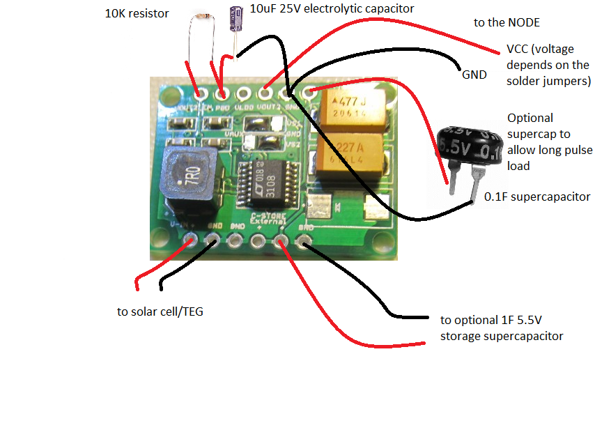
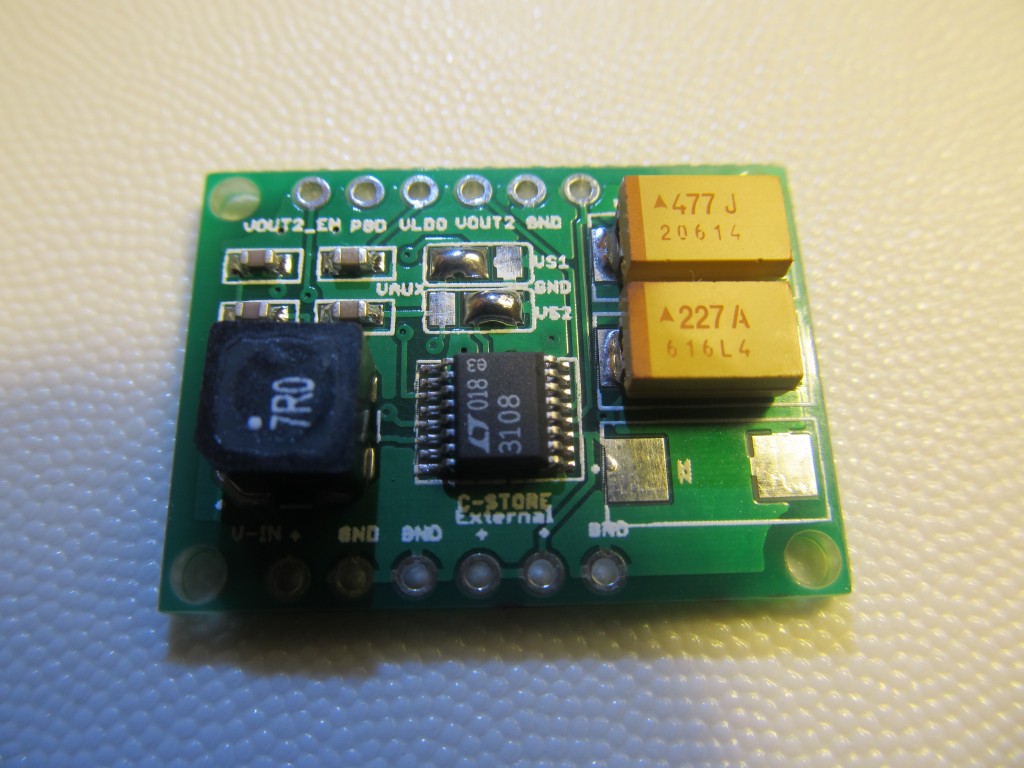
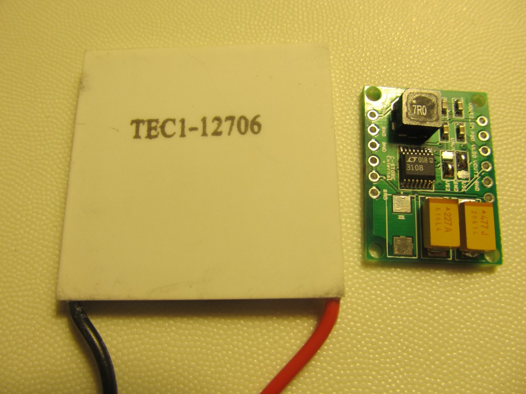
The LTC3108 is a highly integrated DC/DC converter ideal for harvesting and managing surplus energy from extremely low input voltage sources such as TEGs (thermoelectric generators), thermopiles and small solar cells. The step-up topology operates from input voltages as low as 20mV. Using a small step-up transformer, the LTC3108 provides a complete power management solution for wireless sensing and data acquisition. The 2.2V LDO powers an external microprocessor, while the main output is programmed to one of four fixed voltages to power a wireless transmitter or sensors. The power good indicator signals that the main output voltage is within regulation. A second output can be enabled by the host. A storage capacitor provides power when the input voltage source is unavailable. Extremely low quiescent current and high efficiency design ensure the fastest possible charge times of the output reservoir capacitor.
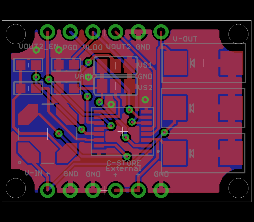
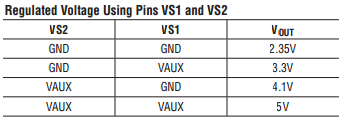
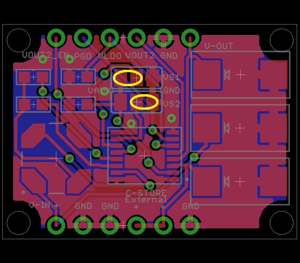
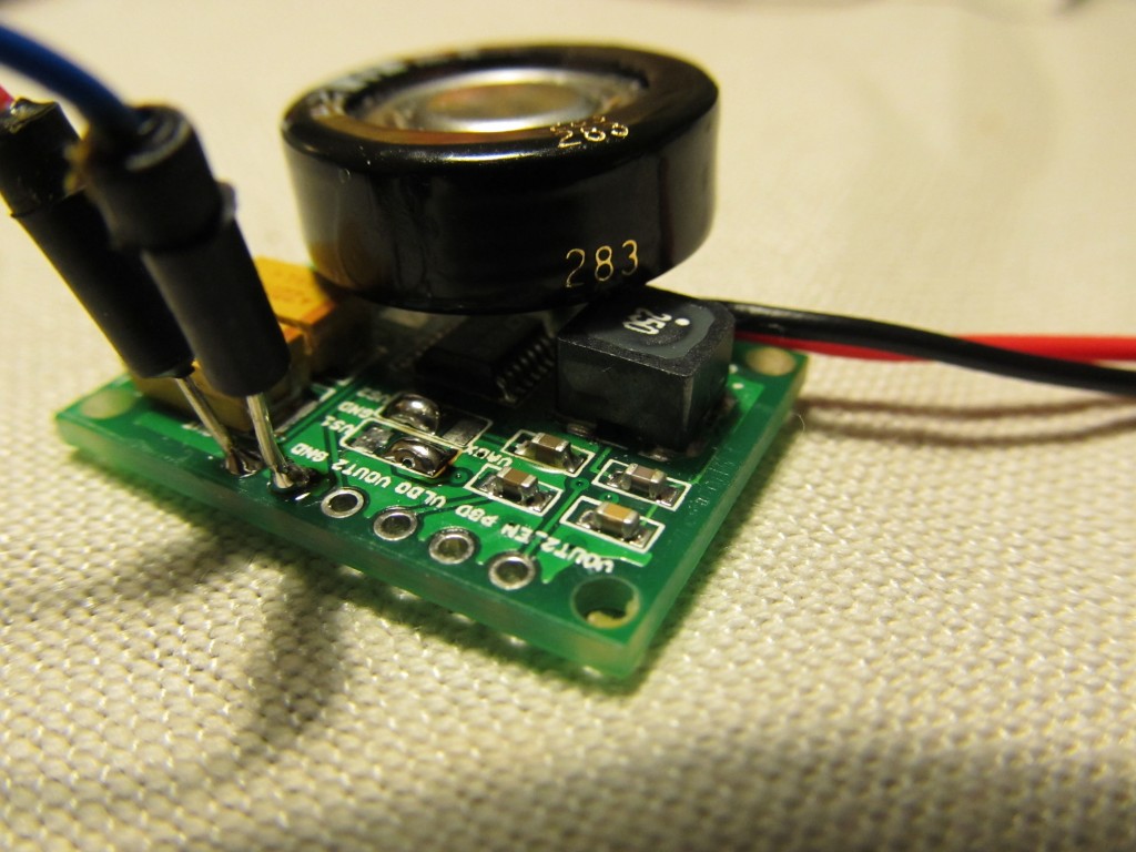
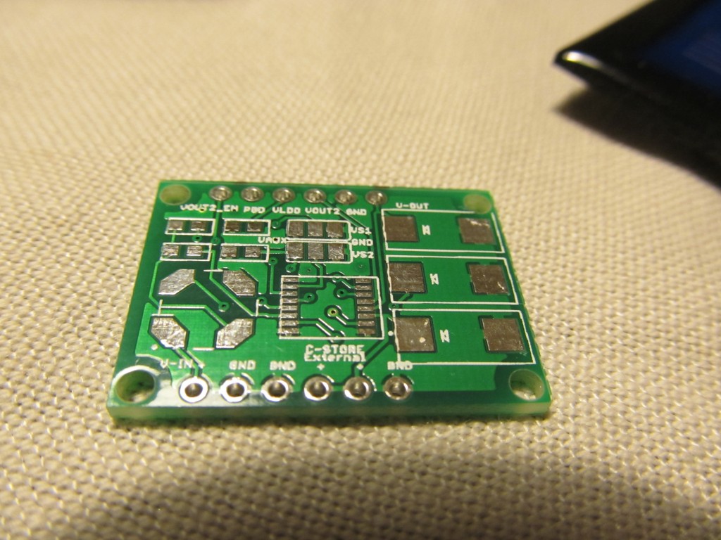
Selecting the VOUT voltage is done by connecting the two solder jumpers on the board as follows:
For example to chose 3.3V for VOUT, the solder jumpers must be configured as shown:
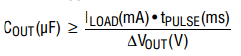
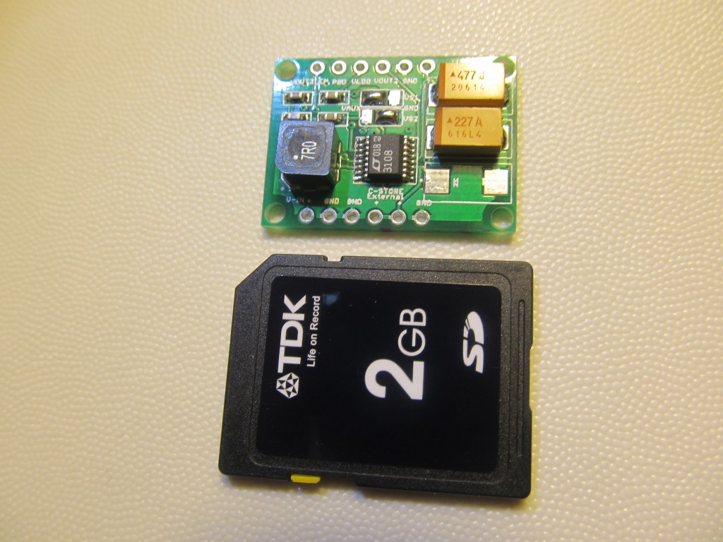
Primary application of the breakout board would be to provide power for small pulsed load applications, i.e. remote sensors that will periodically wake up, make a measurement and transmission and then go in sleep mode to allow sufficient amount of energy to be accumulated for the next pulse. The VOUT capacitor should be sized to provide the necessary current when the load is pulsed on. The capacitor value required will be dictated by the load current, the duration of the load pulse, and the amount of voltage drop the circuit can tolerate. The capacitor must be rated for whatever voltage has been selected for VOUT by VS1 and VS2.
A remote node (Funky, JeeNode etc low power nodes) that utilizes a RFM12B transmitter typically makes a transmission for 5ms and uses 25mA. We can afford to drop the voltage from 3.3V to 3V (or even 2.7V) or delta VOUT=0.3V. The minimum value for COUT capacitor then calculates to 416uF or the closest standard 470uF value can be used. Of course, by assuming the voltage drop to 0.5V (perfectly acceptable for Funky and JeeNode) a smaller COUT value can be used. To be on the “safe” side, I will use 470uF tantalum capacitors for COUT. You can solder additional capacitor in addition to the on-board one to increase the pulse time. I have experimented with soldering a 0.1F supercap on top the 470uF capacitor and achieved great results.
Note that there must be enough energy available from the input voltage source for VOUT to recharge the capacitor during the interval between load pulses. Reducing the duty cycle of the load pulse will allow operation with less input energy.
CIN capacitor is fixed to 220uF as recommended in the datasheet.
The board has a footprint for a third SMD tantalum capacitor for VSTORE, but that is optional to solder. In the majority of cases, a super capacitor rated at least 5.5V would be a more appropriate storage for the excess energy. In my tests I used a 1F super capacitor. The Storage capacitor will provide power to the system in case the input voltage is lost, i.e. at nights if using a solar cell. Using storage capacitor may not be necessary, if running on TEG as these provide constant input power.
VLDO is the output of the 2.2V LDO; It is intended to power a MCU that will monitor the Power Good (PGD) pin and enable (by setting VOUT2_EN to high) the VOUT2 that in its turn will power an external RF module.
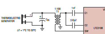
There will be two build options: one for Peltier cell and another for Solar cell. The difference is as per the datasheet recommendations:
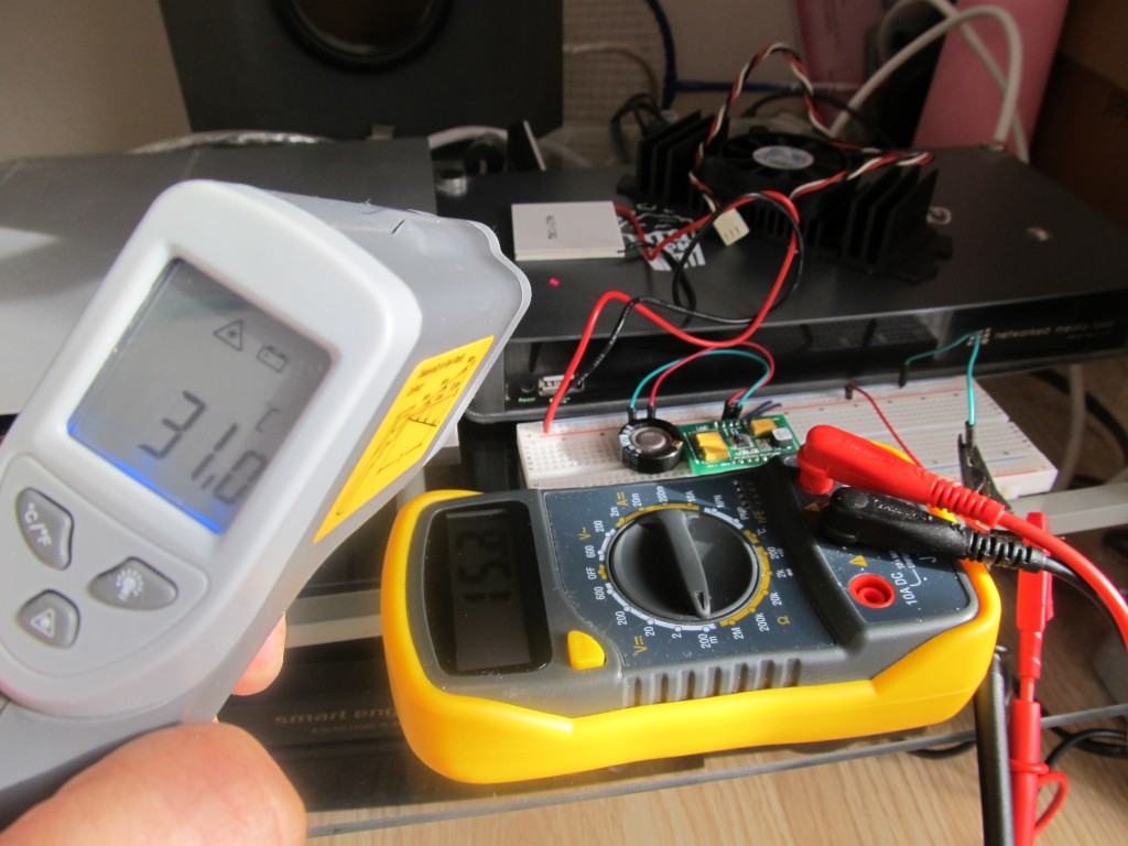
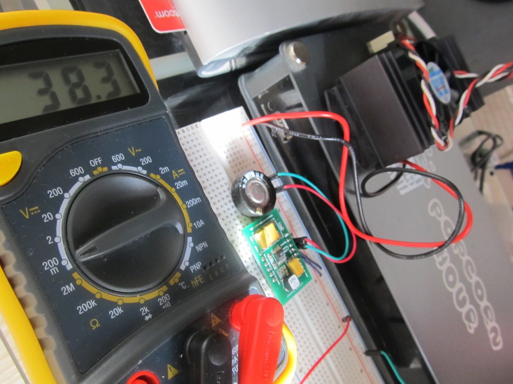
Build A) “Peltier cell” build will have 1:100 ratio transformer, 1nF value for C1
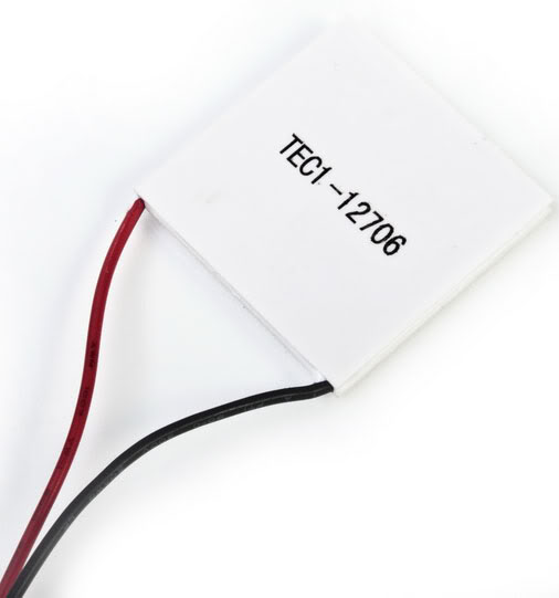
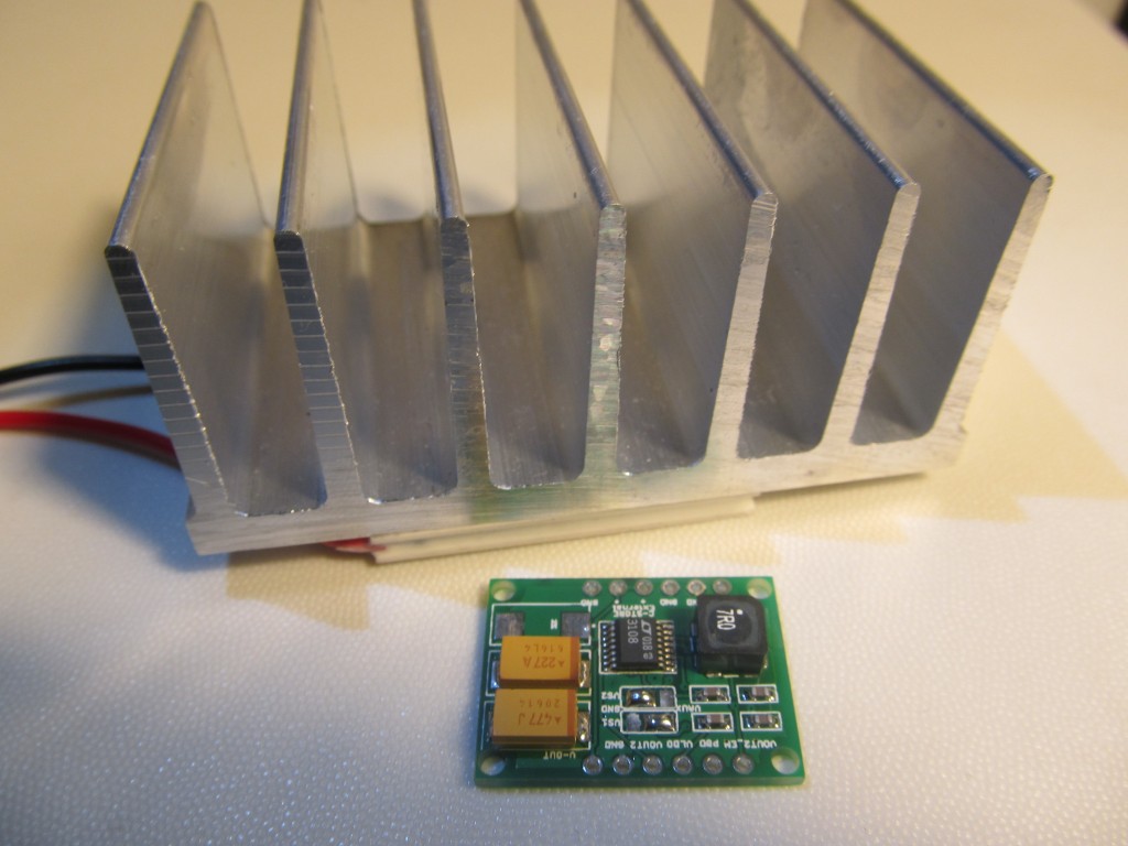
When using with a Peltier element, you need to find a surface where temperature difference can be utilized. I have IR thermometer that I used to look for such places around my house, no surprise to find that the best sources of heat are power supplies. I have a home entertainment network media center that is around 30-35 degrees C at its surface and by placing the Peltier on top of it with an aluminium heat sink, I get excellent results. Note that you don’t necessary need heat, what you need is temperature difference between the two plates of the element. I tested inside a fridge where the temperature on the wall where the coolant flows is -20 degrees C and the inside of the fridge is +5 degrees C; That creates excellent power output too.
This build starts up at 20mV input and is optimized for use with a Peltier element. It will work with a solar cell too, but at the cost of decreased efficiency i.e. slower recovery time, but it will start up at much lower light level, so it is a balance decision.
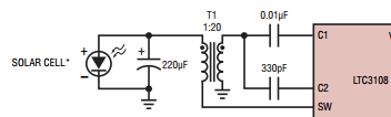
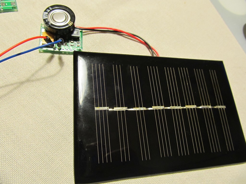
Build B) “Solar cell” build will have 1:20 ratio transformer, 0.01uF for C1
The LTC3108 converter can also operate from a single photovoltaic cell (also known as a PV or solar cell) at light levels too low for other low input voltage boost converters to operate. However, many variables will affect the performance in these applications. Light levels can vary over several orders of magnitude and depend on lighting conditions (the type of lighting and indoor versus outdoor). Different types of light (sunlight, incandescent,
fluorescent) also have different color spectra, and will produce different output power levels depending on which type of photovoltaic cell is being used (monocrystalline,
polycrystalline or thin-film). Therefore, the photovoltaic cell must be chosen for the type and amount of light available. Note that the short-circuit output current from the
cell must be at least a few milliamps in order to power the LTC3108 converter.
This build starts up at 100mV input and 3-4mA current.
I haven’t tested this particular model, but these cells look excellent for the purpose.
See this post for usage with Power Good pin enabling VOUT2. To use this setup, connect the board as follows:
The advantage of the above setup is that it will only power up the attached node when voltage reaches the pre-set with jumpers level and will power off once it drops below.
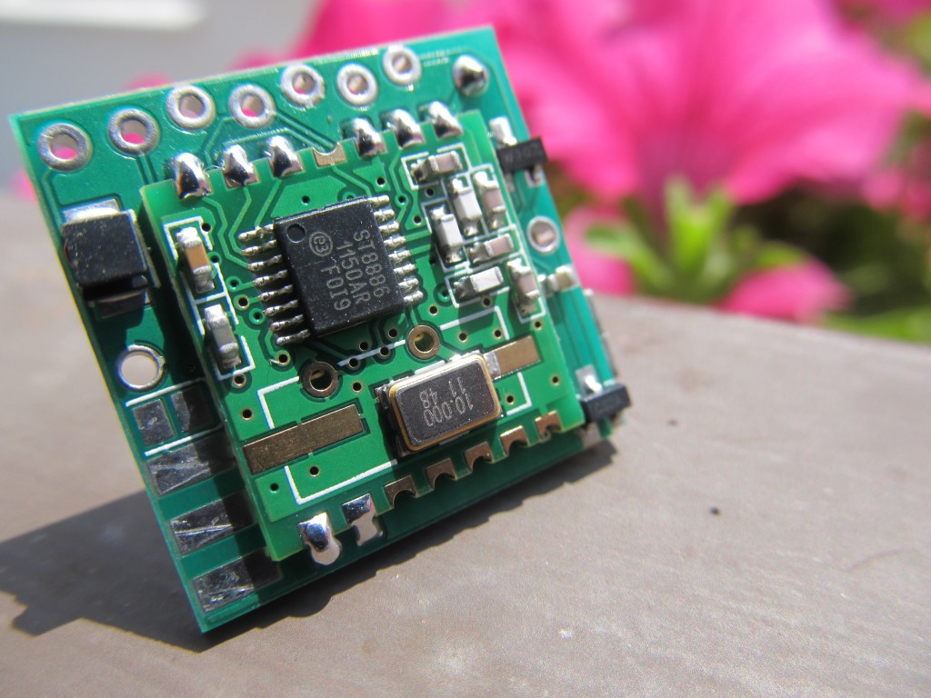
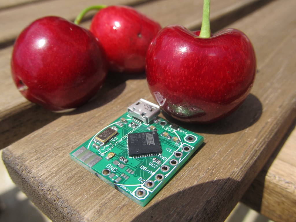
The “Funky v2” is a miniature open source/hardware cut-down clone of the Arduino Leonardo with RFM12B radio module. It is intended as low power, battery operated remote sensing node with USB interface. Due to the miniature size, only few carefully selected pins are available at the side header, none the less that is more than sufficient to interface several sensors at a time.
Having gained experience with my Funky v1 project, I decided to create a new version. The Funky v1 project is a success, yet the areas I wanted to optimize are:
The Attiny84 MCU that was used in the Funky v1 has limited RAM and sketch memory
The Attiny84 requires an ISP programmer for sketch uploading
Many of the available Arduino libraries are not compatible with Attiny84
So the Funky v2 was created, see my posts here , here and here
Board size is 20×21.2mm (0.78″x0.83″) in size (same as Funky v1)
The MCU used in an Atmega32U4, the same MCU that Arduino Leonardo uses. This makes the Funky v2 a minuature Arduino Leonardo compatible board with RFM12b transciever module
The Funky v2 has the Caterina bootloader, so programming is done with Arduino IDE via micro USB cable
Uses external 8Mhz crystal (can switch to internal RC clock in software as described here)
Operates on 3.3V
Weights only 3 grams
Funky v2 is available for sale in limited quantities in the shop.
Note the added MOSFET to control the RFM12B’s power state; This requires explicitly powering up RFM12B transciever before initialization:
pinMode(A5,OUTPUT); // RFM12B power control pin9
digitalWrite(A5,LOW); //Make sure the RFM12B is on (LOW is on)
delay(20); // Allow for RFM12B to start
....RFM12B initalization code here.......
Setting up Arduino IDE for the board
Funky v2 r2 will have the Caterina bootloader and will identify itself as an Arduino LilyPad USB. The purpose of this is to have Arduino IDE support for the Funky v2 without the need of any additional setup. Both Arduno LilyPad USB and Funky v2 operate on 3.3V @ 8Mhz, so it is important to select that board type and not the Arduino Leonardo that runs on 16Mhz. Simply plug in the Funky v2 and when asked for drivers (Windows), navigate to the Arduino/drivers folder.
Older Funky v2 revisions need to use the Arduino Fiov3 drivers. The ZIP file includes instructions on using them.
Powering the board
Note: The micro-USB connector is soldered on the board — not through it. Be gentle when plugging and unplugging your USB cable.
The board can be powered from the micro USB plug and will regulate that input to 3.3V using the the Torex XC6206 LDO regulator included on the board (Funky v2 used MCP1700 LDO prior to Aug 14th 2013, see my post here) . The VUSB line is exposed as a pin on the side header, meaning that you can power the board from there too, just do not exceed the 6V limit that the ATMega32U4 VUSB has. The XC6206 dropout voltage according to the datasheets is 250mV meaning the minimum supply voltage when powering via the VUSB should be 3.3V+0.25=3.55V, so LiPo batteries can be also used as well.
The board carries an option for the LTC3525ESC6 (3 or 3.3V versions) boost regulator and supporting elements to be included, this is useful when you wish to power the board from a 0.8 – 5.5V source and get that regulated to 3.3V. I use that option to power the Funky v2 from a single AAA battery.
The board can also be powered from a single CR2032 battery, but unlike the Funky v1 the battery holder now can only be soldered at the side where the RFM12B module lays as the micro USB connector stands on the way on the reverse side. See example of this setup here.
Running on battery is one one of the advantages of the Funky v2 project, however it needs taking special care to reduce power usage and therefore prolong battery life. Using this example sketch I managed to bring the power consumption down to 0.02mA @ 3V in sleep mode.
NOTE: Please remove any battery attached when plugging into USB.
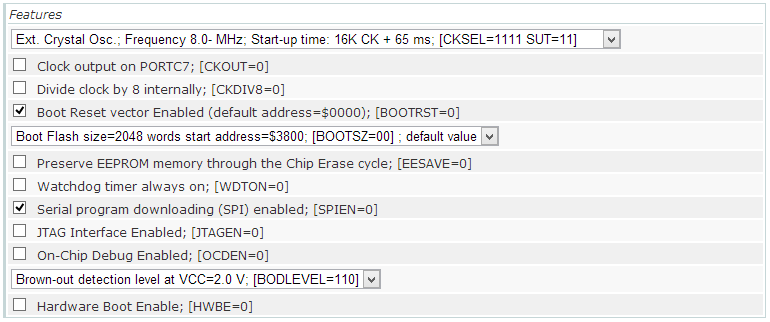
The default fuse settings I use are the same as Arduino LilyPad USB:
You could disable the BOD fuse to save extra 0.02mA in sleep mode.
The bootloader also slightly differs from the “stock” Caterina bootloader because it passes control to the sketch immediately on board power-up and will only go in bootloader mode for 8 seconds on external reset (or if no sketch is present). This is done so that no time is lost between board power-up and the sketch powering down the unused peripherals. Source code of the bootloader here.
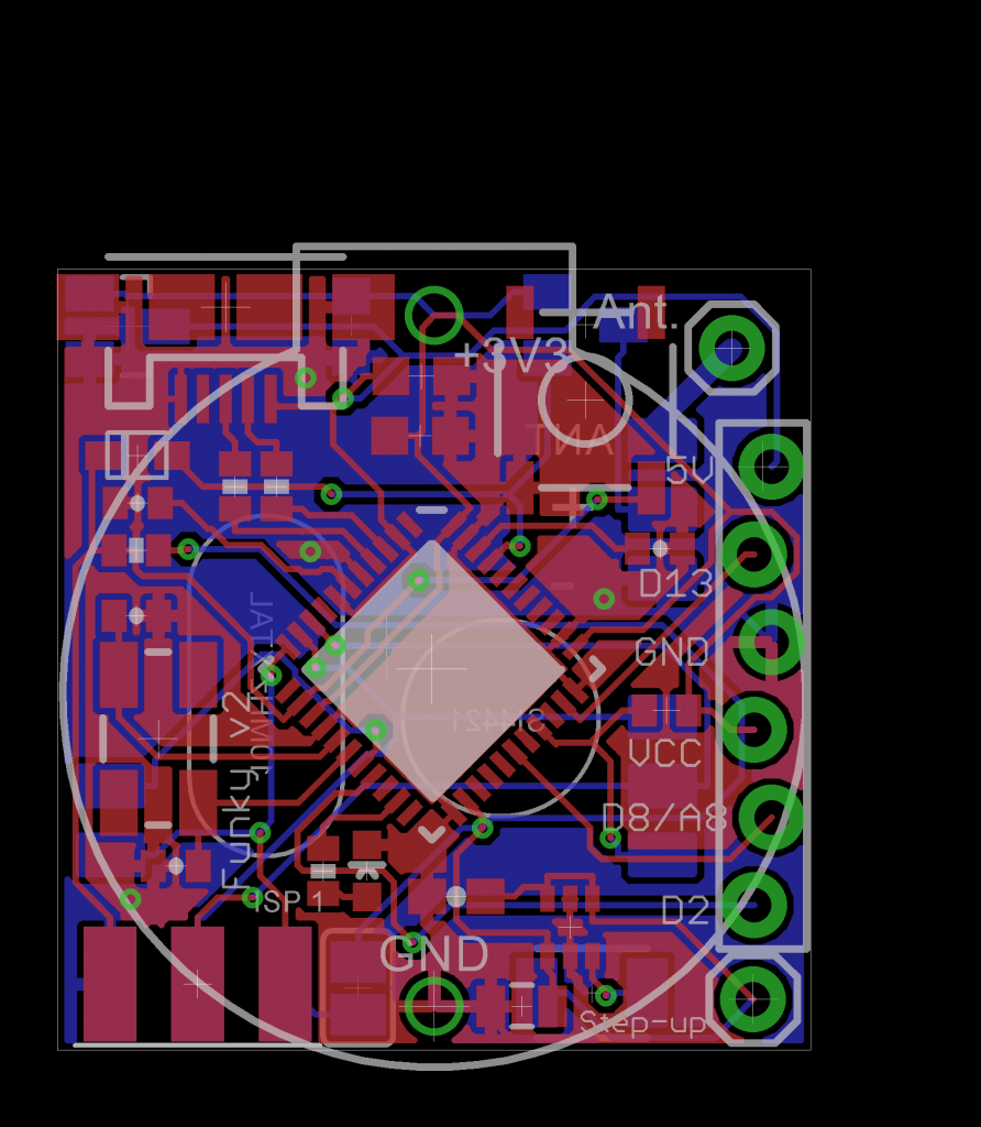
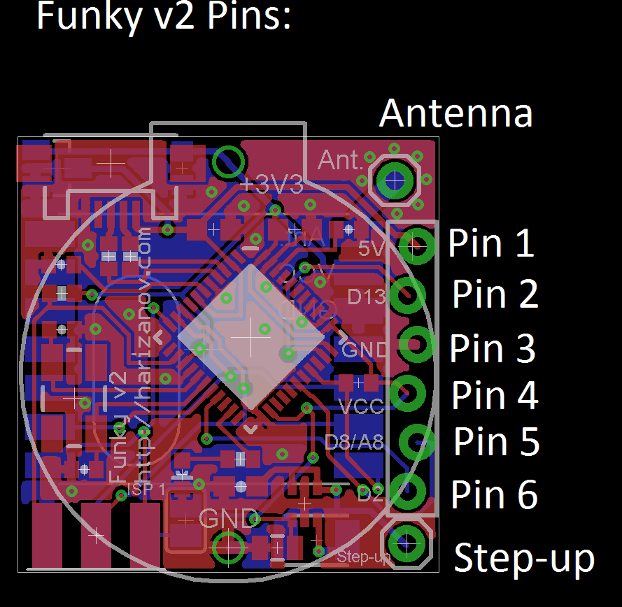
Funky v2 header pins
The side header of the Funky v2 started as intended Jeelabs’s JeePort, but that changed slightly as I advanced with the design. The reason for that is that JeePorts are Atmega328 specific and there is no information on which pins JCW will use in a future Atmega32u4 (if ever) based JeeNode. I still kept the overall idea of having a VCC-DIO-GND-3.3V-AIO-IRQ concept. Having said that, the Ports library will probably work with minor modifications.
Pin 1 connects to VUSB and provides +5V if the USB cable is plugged in. It can also be used to power the board from a 3.5-6V source, given the USB cable is disconnected. Typical application of this pin would be to provide 5V for sensors attached to the header
Pin 2 connects to Digital 13, a special pin with timer output to drive IR LEDs for example.
Pin 3 connects to GND
Pin 4 connects to VCC (3.3V if powered via the USB or the voltage that your battery is providing if powered by a battery)
Pin 5 can be used both as Digital 8 or Analog 8 in Arduino IDE, it is a pin that supports pin-change interrupts: Needed for RX of SoftwareSerial (TX can be digital any pin)
Pin 6 is Connects to Digital 2 pin, also can be used for IRQs
The on-board LED is connected to Digital 1
Detecting USB connection
This is useful when determining weather we are running on battery power or USB power and take measures to reduce power consumption if we are running on battery. See my full post here.
void setup(){
  USBCON = USBCON | B00010000;
  pinMode(1,OUTPUT); // The on-board LED

  delay(550);  // Wait at least 550ms,may even require more on slow hosts (necessary)

  if (UDINT & B00000001){
  // USB Disconnected code here
  digitalWrite(1,HIGH);
  }
  else {
      // USB is connected code here
     digitalWrite(1,LOW);
  }
}

void loop(){
}
Power saving techniques
When running on battery, we aim to cut power consumption down as much as possible. The following code will bring Funky v2 to about 0.03mA sleep current when running with BOD fuse disabled and at 4Mhz. Also see a complete example on GitHub.
  ADCSRA =0;
  power_adc_disable();
  power_usart0_disable();
  //power_spi_disable();  //do that a bit later, after we power RFM12b down
  power_twi_disable();
  power_timer0_disable();   // Will also kill timekeeping, so be careful if your code relies on millis(); comment out if these are needed.
  power_timer1_disable();
  power_timer3_disable();
  PRR1 |= (uint8_t)(1 << 4);  //PRTIM4
  power_usart1_disable();

  // Switch to RC Clock
  UDINT  &= ~(1 << SUSPI); // UDINT.SUSPI = 0; Usb_ack_suspend
  USBCON |= ( 1 <<FRZCLK); // USBCON.FRZCLK = 1; Usb_freeze_clock
  PLLCSR &= ~(1 << PLLE); // PLLCSR.PLLE = 0; Disable_pll

  CLKSEL0 |= (1 << RCE); // CLKSEL0.RCE = 1; Enable_RC_clock()
  while ( (CLKSTA & (1 << RCON)) == 0){}	// while (CLKSTA.RCON != 1);  while (!RC_clock_ready())
  CLKSEL0 &= ~(1 << CLKS);  // CLKSEL0.CLKS = 0; Select_RC_clock()
  CLKSEL0 &= ~(1 << EXTE);  // CLKSEL0.EXTE = 0; Disable_external_clock

   // Datasheet says that to power off the USB interface we have to:
   //      Detach USB interface
   //      Disable USB interface
   //      Disable PLL
   //      Disable USB pad regulator

   // Disable the USB interface
   USBCON &= ~(1 << USBE);

   // Disable the VBUS transition enable bit
   USBCON &= ~(1 << VBUSTE);

   // Disable the VUSB pad
   USBCON &= ~(1 << OTGPADE);

   // Freeze the USB clock
   USBCON &= ~(1 << FRZCLK);

   // Disable USB pad regulator
   UHWCON &= ~(1 << UVREGE);

   // Clear the IVBUS Transition Interrupt flag
   USBINT &= ~(1 << VBUSTI);

   // Physically detact USB (by disconnecting internal pull-ups on D+ and D-)
   UDCON |= (1 << DETACH);

   power_usb_disable();  // Keep it here, after the USB power down
   rf12_initialize(storage.myNodeID,storage.freq,storage.network); // Initialize RFM12
   // Adjust low battery voltage to 2.2V
   rf12_control(0xC000);
   rf12_sleep(0);                          // Put the RFM12 to sleep

   power_spi_disable();
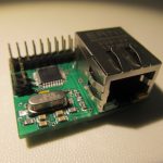
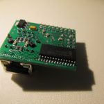
The Micro Internet of Things Gateway (uIoT) is a Atmega328 + ENC28J60 solution, one of many using this combination of hardware, but still unique with its miniature size (38mm x 28 mm and 15 mm in height). The original board is designed by Simon K. and I have his permission to develop it further and sell my version to hobbyists. My revisions so far include adding a micro USB plug for power purposes and re-shuffling the header so plain rectangular shields can be created more easily.
I have also developed a shield that plugs on top the uIoT and adds a RFM12B connectivity, a Micro SD card slot, a LED and FTDI connector option.
You can set the fuses to run on the internal RC oscillator at 8Mhz, this is my recommended setup. To achieve this, I use a modified OptiBoot Bootloader optimised for 38.4kbps baud. The modified and compiled version can be downloaded from my github repository. The full guide of how to modify and re-compile Optboot is detailed on the Arduino forums here.
In order to compile Arduino sketches to work for this modified bootloder we need to add a new entry in Arduino’s boards.txt.
Now we just need to select board > ATmega328 Optiboot @ 38,400baud w/ 8MHz Int. RC Osc in Arduino IDE when compiling sketches.
The board can be clocked via the CLKOUT pin of the ENC28J60, meaning it can run on 6.25Mhz or 12.5Mhz depending on how you set the prescaler. Upon power-up, the board always starts on 6.25Mhz and with small modification to the EtherCard library, you can run on 12.5Mhz. In this case the board requires custom entries in the boards.txt, if you plan to use it in the Arduino IDE; see here, here and here
The board uses digital 10 as CS for the ENC28J60
The shield uses non-conventional pin for selecting the RFM12B module, that also requires changing 3 lines in the Jeelib’s RFM12.cpp definitions; I would include a modified version in the examples on github to eliminate the need for change by the end user.
I have adapted optiboot and 2boots bootloaders for the uIoT, but using these only makes sense if you have the shield on (because of the FTDI connector)
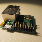
The RFM2Pi board is an Attiny84+RFM12b based expansion board that plugs on top the Raspberry Pi‘s GPIO pins and provides serial interface with the RFM12b module. The board is pre-programmed with RFDemo sketch for Attiny84 and will output to Pi’s UART the incoming packets. This revision of the board is created in collaboration with openenrgymonitor.org
The interface is bi-directional, that means the board can be configured and used to send Jeelib compatible packets as well. Software running on the Raspberry Pi side can parse and decode the serial input and make further processing, like posting to emoncms or cosm. Here is an example of capturing and decoding in perl: link. The latest modular emoncms version has add-on module to support the RFM2Pi board.
Note: Prior to going any further, please backup Raspberry Pi’s SD card
By default, you Raspberry Pi will be running the console on the UART. In order to use it for the RFM2Pi board, we need to free it up from the console:
Make sure Raspberry Pi’s UART is disconnected from the console and available for programs to use it
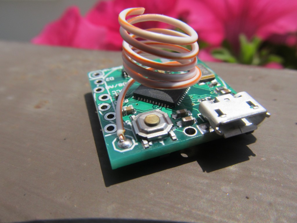
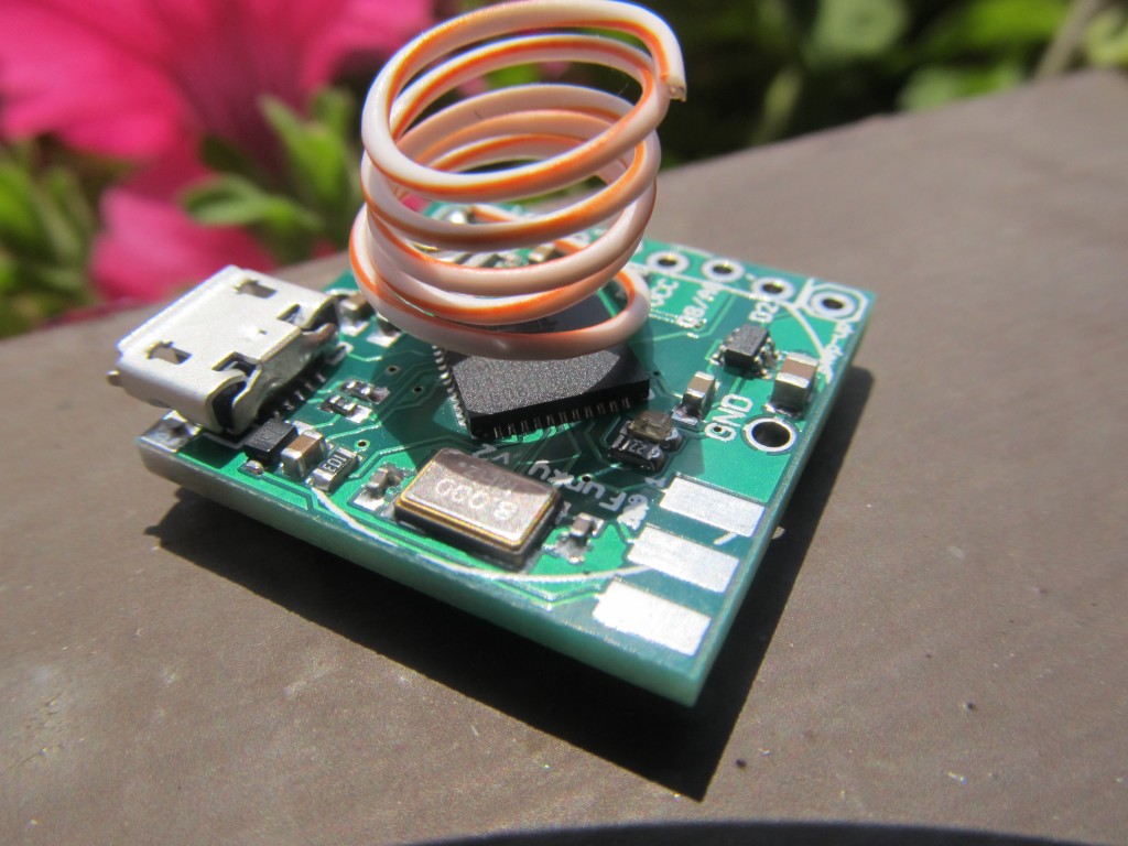
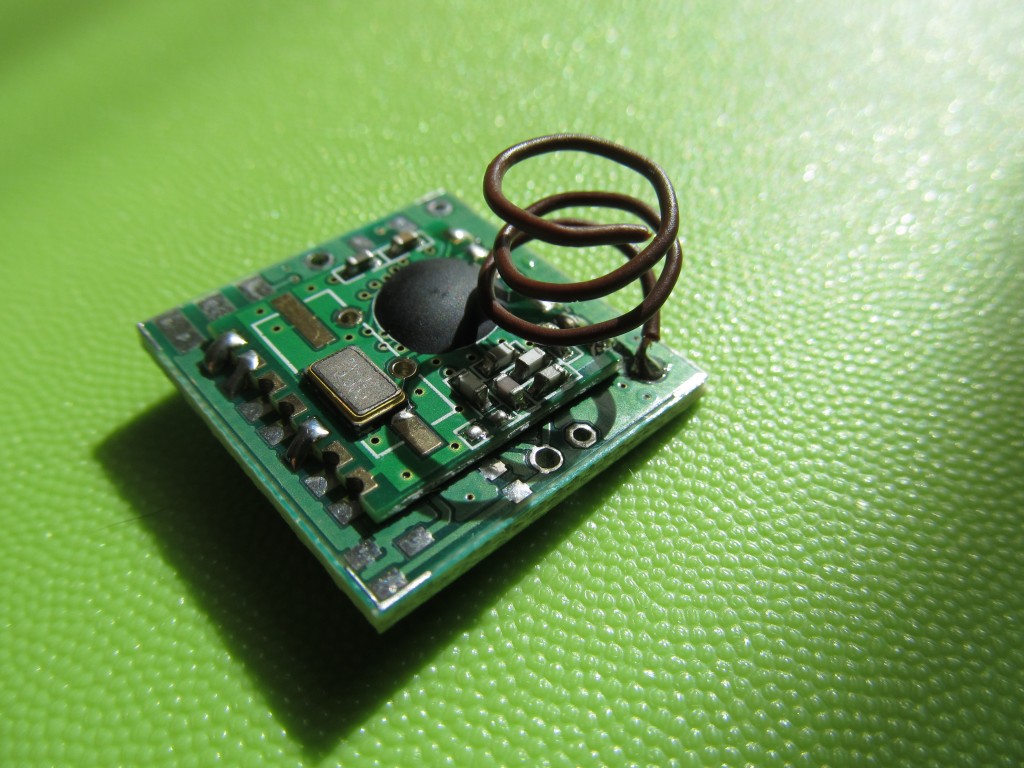
The ‘Funky’ Sensor is a miniature ATTiny84 based node with a RFM12b module for wireless communications. It was originally created by Tobias Floery, and inspired by Jeelab’s JeeNode Micro. I was quite impressed by the small size and usability of the device and asked Tobias for permission to copy and develop further a version of my own.
My revisions include
Added voltage step-up circuit based on the LTC3525 boost regulator chip , the exact same as the one found on Jeelab’s AA power board.
Removed the battery voltage sensing circuitry as it can be achieved using the bandgap method
Added micro-USB plug, so that the node can be powered from there (only power function, no USB communication). The voltage regulator is retained, so alternatively the Funky can be powered from a source up to 7.5V
I added provision for a 4.7K or 10K between pads 4 and 5 on the Funky, that will allow directly soldering DHT22 humidity+temperature or DS18B20 temperature sensors (or any other sensor that uses three pins and requires pull-up on the data line).
The board measures 23 x 23.4 mm in size. I use the “flat crystal” version of the RFM12b module to keep it low-profile and to allow the optional CR2032 battery holder to be soldered on either side.
Because of its miniature size, I only offer pre-built Funky sensors in the store.
Programming the Funky
You need to set-up the Arduino IDE for use with ATTiny processors. I have shared my experience in this post. My already configured Arduino IDE 1.0.1 for Windows is available for download here.
You need a six pin ISP programmer to program the Funky. I own a clone of the USBTiny programmer, these are widely available on ebay and cost less than 10 dollars delivered.
Note: The Funky is a 3.3V device, and the RFM12b module cannot withstand more than 3.6V. When programming the Funky, make sure you don’t supply 5V thru the ISP programmer, or the RFM12b module will most likely be burned. The USBTiny programmer has a jumper on it that when removed, does not provide power to the ISP connector. You still have to provide 3.3V from other source so that the Funky can be programmed.
You need 6 pin ISP connector to program the Funky. The PCB is 1.60mm thick, while a 2×3 pin header has 2mm spacing. It requires a small bending to make better contact, use pliers to apply minimal pressure to the pins so they make better contact:
Prior to uploading a sketch, make sure you have set the correct fuses. I recommend running the Funky on the Internal Oscillator at 8 Mhz, because 1Mhz is not enough for sending/receiving RFM12B packets. Setting the fuses is done by selecting the appropriate desired option and then pressing “burn bootloader”. This doesn’t really burn a bootloader, only sets the correct fuses for this type of board. You only need to to this once, fuse settings are then “remembered”; Since I ship the Funkys already pre-programmed with a test sketch, I have already set the fuses to 8Mhz BOD disabled for you.
You can run the Funky on RFM12b’s crystal @ 10Mhz as described here, but only do this if you absolutely know what you are doing because you may end up with unresponsive Funky.
The TinySensor is a ATTiny84 based multi-purpose board. It is designed to primary serve as a low power, battery operated wireless remote sensor that will measure and transmit data to a remote base at regular intervals. For the purpose, there is a dedicated temperature sensor port (intended for DS18B20 one-wire temperature sensor bus) and a configurable voltage divider.
Numerous applications and hardware configurations are possible, some examples include
Temperature sensing
Air Humidity Sensing
Light Intensity sensing
Current sensing (for power monitoring)
Soil Moisture sensing
Water flow sensing
Switch position sensing
..and many more, limited by your imagination only. See my projects tagged with Attiny84
The module has on-board RFM12B transceiver module, so it is able to communicate with other modules in the wireless network.
Additionally, there is a SD card pin connector, that allows storing measurement data on a SD card, in really remote locations that may be useful option.
There is a Jeelabs JeePort, so you can benefit from all JeePorr compatible sensors /libraries out there
A 3.3V FTDI connector can be used to power the board and serial bi-directional debugging (no programming yet)
A CR2032 battery slot can be used to power the board when the application permits ultra-low power mode and long intervals between transmissions of data.
A Raspberry Pi connector allows plugging the TinySensor directly on a Raspberry Pi and using UART to communicate between the two modules. A good example usage is the RFM12b to Raspberry Pi serial gateway project.
Building it
Building the TinySensor is pretty much trivial. Start with the lowest profile components and gradually add them in the order of height, this way the taller components won’t stand in the way.
I usually start with the 10K resistors that keep the ATtiny84 reset and RFM12B’s Slave Select lines pulled up. If you will not use the ISP for programming, these two resistors may be omitted.
If you intend to use the DS18B20 temperature sensor, you need to solder the 4K7 resistor that keeps the data line pulled up. I prefer to add headers instead of soldering the other resistors, so that I can change configurations on the run.
Next, solder in the two decoupling capacitors. These are ceramic and orientation doesn’t matter.
I then solder the RFM12B module on the bottom of the PCB. The orientation of the RFM may be a bit tricky to figure at first. The crystal needs to go on the inner side of the pcb. Apply a small amount of solder on one of the pins so that it affixes the whole module. Adjust if necessary so it is in the middle of the footprint. Once positioned, solder carefully all connections. I hold the soldering iron a bit longer when soldering the RFM12Bs so that solder falls in the bottom of the module as well. Make sure there is solder on the top of the pad as well, I have had issues where I didn’t have enough solder applied. The antenna needs to be 82mm for 868Mhz modules.
You can now solder a 14 pin socket (or the ATTiny84 directly, if you need low-profile, but the socket is recommended for most uses) and the ATTiny84. The silk screen shows the correct orientation of the socket and the chip.
Next is the 6-pin ISP connector, if you will use it to program the ATtiny.
This is the basic configuration to get you started
Note: Prior to doing any further work, please backup Raspberry Pi’s SD card.
The TinySensor has a dedicated port sized 2×5 pins, that allows it to be plugged on a Raspberry Pi. It will get its power from the 3.3V line and will connect Pi’s UART TX and RX TinySensor’s PA3 and PA7 respectively.
When plugging the TinySensor on the Raspberry Pi, make sure of the following:
The TinySensor board is held on the Pi by the 2×5 pin header only. If pressed, it may contact the Pi’s other components. I apply a small amount of hot glue silicon on two points, where potential contact between the TinySensor and the Raspberry Pi may occur, you can use isolation band as well. These points are the FTDI connector (if soldered, the connections are close to Pi’s GPIOs) and between the ISP connector and DS18B20 port, so that the board doesn’t touch the large capacitor on the Pi:
The TinySensor should not be powered from another source.
Don’t plug FTDI cable directly in the FTDI port as it provides 3.3V too. You may use FTDI for serial debugging by connecting it with jumper wires, you need only GNS, TX and RX lines. Leave the FTDI power unconnected
If you have the CR2032 battery installed, please remove it. If you have other batteries installed at the external battery connector, make sure they are disconnected
If you have ISP programmer connected, please make sure it does not power the TinySensor. There is a jumper on most ISP programmers that disconnects the power line
Make sure Raspberry Pi’s UART is disconnected from the console and available for programs to use it


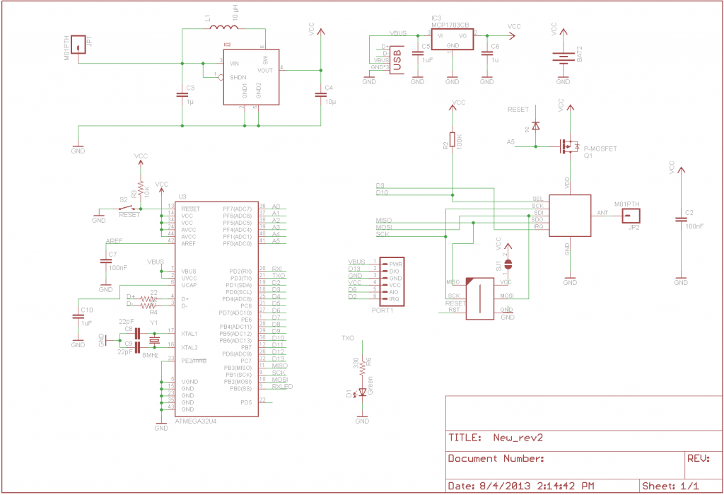
 Schematic
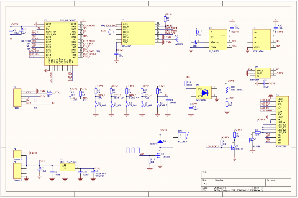


![[OBSOLETE] Three Channel WiFi Relay / Thermostat Board](https://harizanov.com/wp-content/uploads/2015/02/IMG_20150317_110559.jpg "[OBSOLETE] Three Channel WiFi Relay / Thermostat Board")


![[OBSOLETE] Funky v3](https://harizanov.com/wp-content/uploads/2015/01/funky_v3_r3.brd_.png "[OBSOLETE] Funky v3")