
I have been receiving requests to build a SMS doorbell from all around the world ever since my SMS doorbel project got featured on hackaday, damnGeeky, hackedgadgets and few other places . My approach is relatively difficult to follow, so I decided to put up some simple steps for you folks to follow and get even better results than my original project. You will need the following components
- A Raspberry Pi, any model will work. I have mine equipped with a WiFi dongle so that I don’t have to worry about Internet cabling
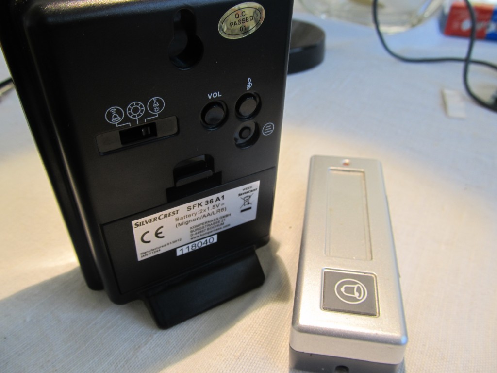
- A wireless doorbell. Any make, any band, just make sure that
- The base runs on 3V, this is really important so that you avoid complicating things with voltage level shifting. You can easily find out if the base is running on 3V, if it is powered by two AA batteries.
- The base has a LED that blinks when the doorbell is activated
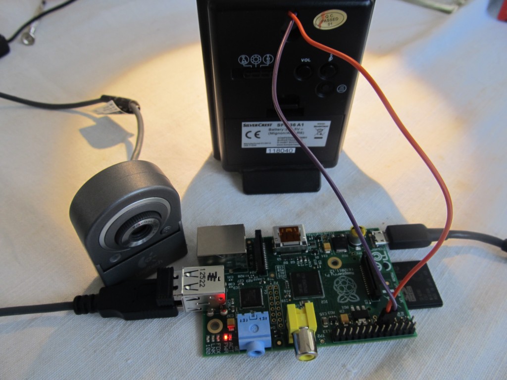
- A USB web camera (optional, if you wish to take a picture of who is ringing your doorbell). Make sure yours is compatible with Raspberry Pi: http://elinux.org/RPi_VerifiedPeripherals
- A 220ohm resistor (optional, added for peace-of-mind)
- Soldering iron
- A GMail account
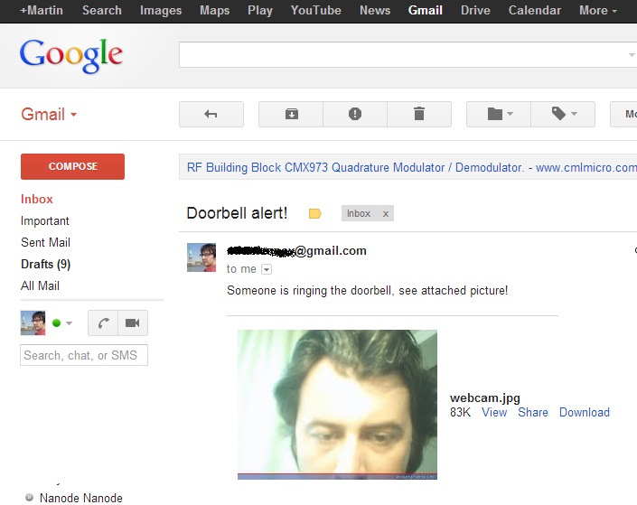
The idea is the following: to tap into the doorbell base’s LED and have a script look for the LED blinking; If it finds it blinking, then someone is ringing the doorbell. We take a picture and email it as attachment. You can then set up a rule in GMail to forward to a email-to-sms service, if you wish, or simply to other email accounts that are connected to your phone, so that you would receive immediate notification.
So lets get hacking. I took my wireless doorbell apart, that was a bit tricky because there were no screws. Mine just snaps together and I had to use a flat screwdriver to snap it open.

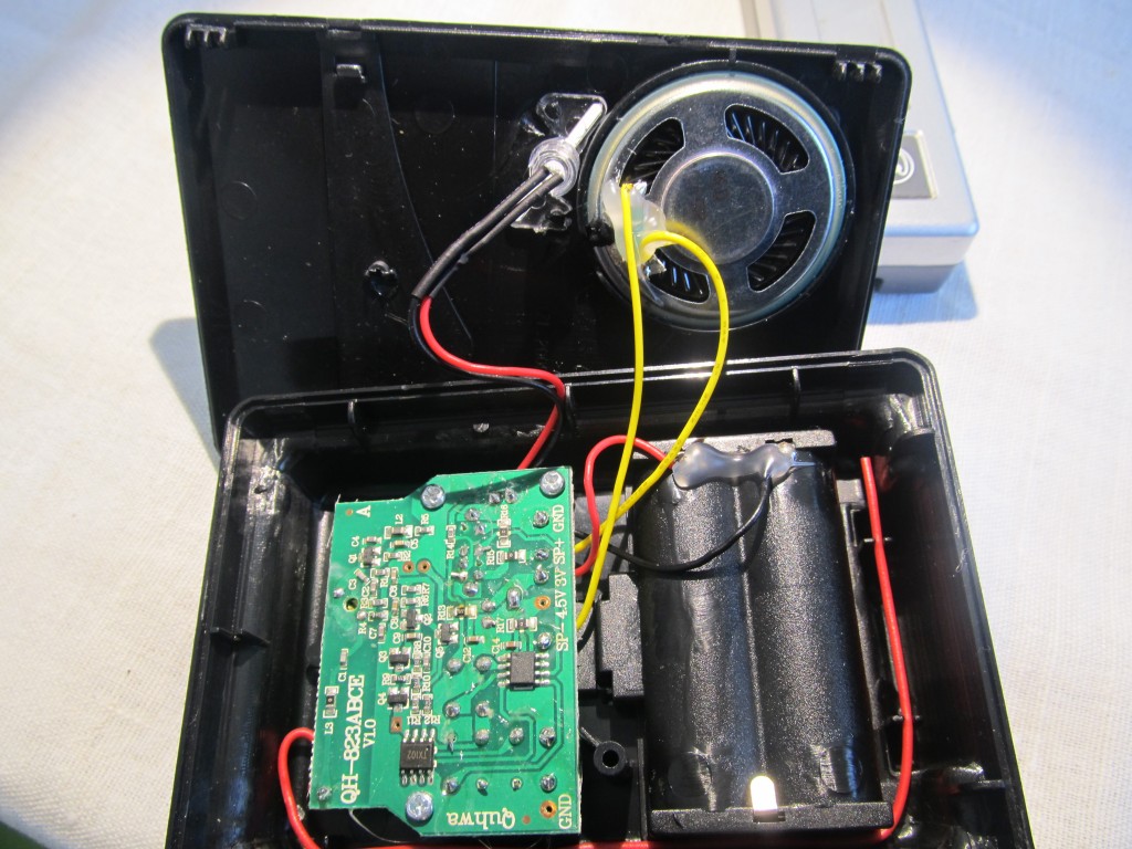
Once opened, look for the leads to the status LED. We need to grab the signal from there and route it to the Raspberry Pi. One lead is the positive and the other negative (anode/cathode of the LED). It is important to get these right, use a multimeter, if in doubt. In my case, the wires to the LED were colored, so I had no doubt which is the positive and which is the negative: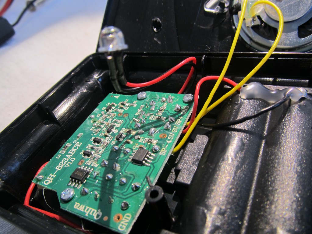
I was curious what kind of signal we get on the LED, so I hooked it to my oscilloscope: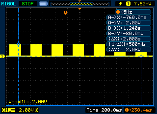
It pulses (actually the pulses depend on the chime chosen) at 2V with some PWM. I thought the PWM may cause troubles, and was prepared to make a low pass filter to remove it, but then it turned out not to be a problem. The reason we needed a 3V base is so that this captured signal doesn’t exceed Raspberry Pi’s 3.3V limit on GPIO pins. A 2V signal registeres as a ‘HIGH’, so we are perfectly good. You don’t need to repeat this step, this is just for my own verification.
Next, I soldered two wires, one to the anode and the other to GND. Common GND is required for this to work. The current to the anode is already current-limited, but for peace-of-mind I added a 220 Ohm resistor in series: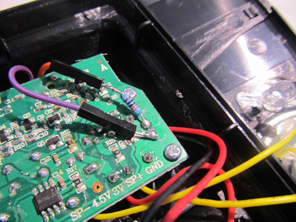
I am done with the hacking part, I now closed the base with the wires leading out of it: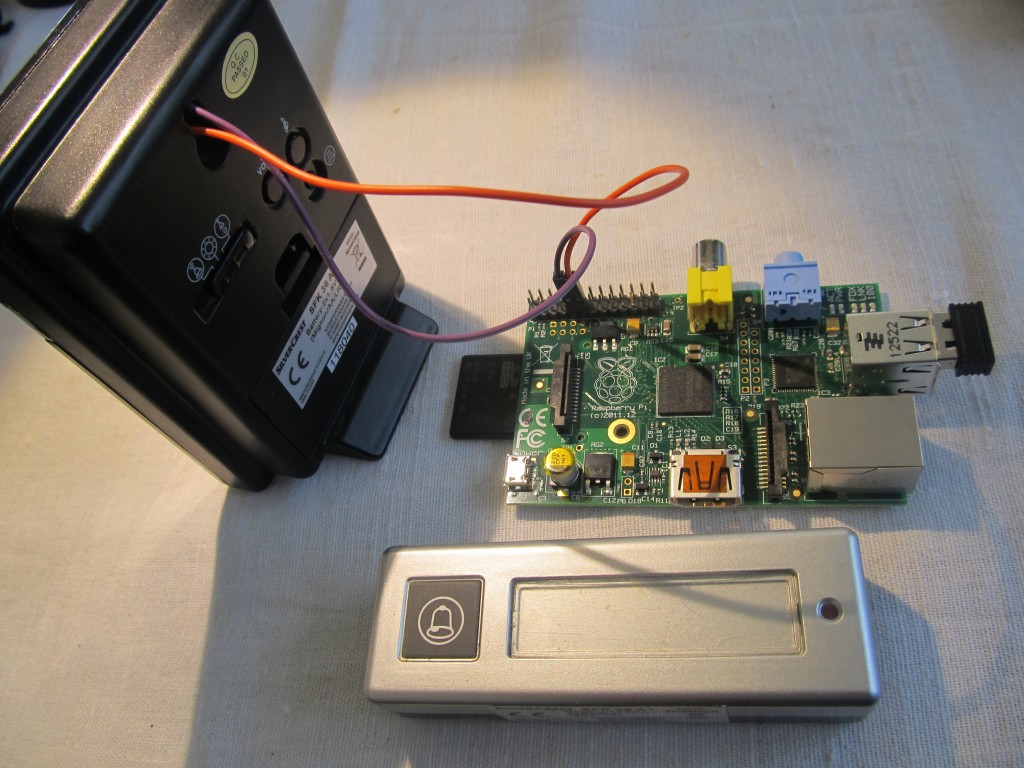
The GND wire connects to some GND pin of the Raspberry Pi and the anode wire connects to GPIO 17. See the GPIO header map, GND and Pin 17 are next to each other: http://elinux.org/RPi_Low-level_peripherals
Now to move on the software part. You will need fswebcam to take the webcam snapshots, this is optional
sudo apt-get install fswebcamNext, create a python script that will watch the state of GPIO pin 17 and take some action when the doorbell brings it to ‘HIGH’. Script for this was taken from here.
nano wait_doorbell.py
and it should look like this:
import RPi.GPIO as GPIO
import time
import os

#adjust for where your switch is connected
buttonPin = 17
GPIO.setmode(GPIO.BCM)
GPIO.setup(buttonPin,GPIO.IN)

while True:
    #assuming the script to call is long enough we can ignore bouncing
    if (GPIO.input(buttonPin)):
        #this is the script that will be called (as root)
        os.system("fswebcam -r 960x720 -d /dev/video0 /home/pi/webcam.jpg")
        os.system("python /home/pi/sendnotify.py")
To have this run upon booting, we need to edit /etc/rc.local (as root since this is the owner).
sudo nano /etc/rc.local
At the bottom, just above exit 0 we’ll add a call to our script.
python /home/pi/wait_doorbell.pyNext, lets create the mailing script, what I used is the “Sending Attachments through Gmail from the Raspberry Pi” script:
nano sendnotify.py
..with the following content, replace the username and password as needed:
#!/usr/bin/env python
import smtplib
from email.MIMEMultipart import MIMEMultipart
from email.MIMEBase import MIMEBase
from email.MIMEText import MIMEText
from email.Utils import COMMASPACE, formatdate
from email import Encoders
import os

USERNAME = "username@gmail.com"
PASSWORD = "password"

def sendMail(to, subject, text, files=[]):
    assert type(to)==list
    assert type(files)==list

    msg = MIMEMultipart()
    msg['From'] = USERNAME
    msg['To'] = COMMASPACE.join(to)
    msg['Date'] = formatdate(localtime=True)
    msg['Subject'] = subject

    msg.attach( MIMEText(text) )

    for file in files:
        part = MIMEBase('application', "octet-stream")
        part.set_payload( open(file,"rb").read() )
        Encoders.encode_base64(part)
        part.add_header('Content-Disposition', 'attachment; filename="%s"'
                       % os.path.basename(file))
        msg.attach(part)

	server = smtplib.SMTP('smtp.gmail.com:587')
	server.ehlo_or_helo_if_needed()
	server.starttls()
	server.ehlo_or_helo_if_needed()
	server.login(USERNAME,PASSWORD)
	server.sendmail(USERNAME, to, msg.as_string())
	server.quit()

sendMail( ["*******your_email********@gmail.com"],
        "Doorbell notification",
        "Someone is ringing the doorbell, picture attached",
        ["/home/pi/webcam.jpg"] )
So now you can reboot to have the background watching script run and test it by pressing the doorbell knob. If all is setup, you will get an email like this in few seconds:
Pingback: Find out who is ringing your doorbell by email with a #RaspberryPi | Raspberry PiPod
Pingback: กดออดไม่ใช่แค่มีเสียง แต่ส่งภาพไปอีเมล์ด้วย | Raspberry Pi Thailand
it great!!! thanks for shared!!
I found the python script that waits for the input to use too much of the CPU. Instead I’m using a simple shell script based on the wiringpi commands. Now my cpu is back at 99% idle. See below.
#!/bin/bash
while true
do
gpio wfi 4 rising
python /home/you/yournotifyscripthere.py
done
Nice! Thanks for sharing
Wynneth,
how does your script work?
when I try it it says gpio command not found?
oh yea you are dealing with a R-PI newb here!!!! 😉
I also noticed the high cpu usage and wanted a way to do it better, not sure why bash handles it better here but it would be nice to implement!.
Never mind I found a way that uses the python code and the cpu is only at 8-10%.
#!/usr/bin/env python
# -*- coding: utf-8 -*-
#import libraries needed
import RPi.GPIO as GPIO
import time
import os
#adjust for where your switch is connected
buttonPin = 25
GPIO.setmode(GPIO.BCM)
#I used the pull_up_down=GPIO.PUD_DOWN because I do not have a 220 ohm resistor currently and it seems to work just fine.
GPIO.setup(buttonPin,GPIO.IN, pull_up_down=GPIO.PUD_DOWN)
while True:
#assuming the script to call is long enough we can ignore bouncing
#added a time.sleep(0.02) which is 2ms to let the cpu breathe and maybe do something else, this is what brought my cpu down.
time.sleep(0.02)
if (GPIO.input(buttonPin)):
#this is the script that will be called (as root)
#os.system(“fswebcam -r 960×720 -d /dev/video0 /home/pi/webcam.jpg”) #commented out as I do not have a webcam currently.
os.system(“python /home/pi/sendnotify.py”)
I haven’t been able to find a door bell that has the LED. Do you think I could use the speaker output for the trigger? I actually don’t even need the door bell to make any sound because I want to use this as kind of a “panic” button. When someone pushes the button, I come running.
you could check the voltage levels, make sure it doesn’t go over 3.3V or less than 0V. You may need to set a low-pass filter too
Xantheus,
I did not use a wireless door chime in my project, I used a simple doorbell button and a battery enclosure from radio shack (part 2700408) it was like $2 put two rechargeable batteries in it (1.2 volt each so 2.4 or 2.7 in my case) wired it in series with the doorbell button and hooked up to the Pi and slightly modified the code which I posted above for the wait_doorbell.py program.
It works great for me! Now all i need to do is make it look a little prettier than it currently is!
In order to bring the cpu usage down even lower and to improve the python loop you can use interrupts with the gpio on the raspberry pi.
this should watch for events on pin2 and do nothing but sleep until the button is pressed. It changes it from constantly checking the button state to just sleeping until it’s interrupted. Makes the script much more reliable in my experience
GPIO.setmode(GPIO.BCM)

GPIO.setwarnings(False)

GPIO.setup(2, GPIO.IN)  # push button
def alert_action(channel):
print('Edge detected on channel %s'%channel)
if channel == 2 :
alertcmd = "/root/pushAlert.py"
GPIO.add_event_detect(2, GPIO.FALLING, callback=alert_action, bouncetime=200)
while True:
sleep(1)
GPIO.cleanup()
I did this and it worked great. Skipped the webcam stuff I just went for logging and had my door chime be an MP3 file played on another pi in the house, great… BUT… then I decided that i wanted to tidy the whole thing up and rip the doorbell receiver to pieces and package the thing inside the pi case (or similar)… I needed to lose the batteries in the receiver unit… So (maybe stupidly) I figured I could use the Pi 3.3 volt pins to power the receiver unit instead of the batter pack. I tried it (took 3v positive and ground from the Pi to the receiver unit battery terminals to test). But then it went nuts, detecting false rings constantly and stuff. Any idea why my plan didn’t work? Possible to power the recevier circuits from the Pi itself ?
The 3.3V power pin on the Pi may not have enough ‘juice’ to power your receiver, it can only source up to 50mA and the receiver may require more than this.
Thanks for your nice tutorial. Works perfect for me!
I have a question: How can i call a shell script from python? (dropbox_uploader.sh)
Hi,
I’d love to replicate this in my home. I currentyly have a wired doorbell rather than wireless. I’ver had a look and the doorbell contains a 9v battery wired into a mecahnical strike that hits a plate when the button is pressed. How would I wire this up to a Pi without damaging it?
I’d use an optocoupler, here is a nice wiring example: http://raspberrypihobbyist.blogspot.com/2012/09/gpio-input-circuit_19.html
Use an optocoupler rated 9V or more, I use Sharp RC817 mostly when I need to do something similar.
The rest should be the same.
It’s been almost 30 years since I had to play around with resistors… Man… As a kid I used to know the colours off by heart.
I think I’ve solved the problem for me with 3 x 3.3K resistors in series, and then placing the series in parallel with the doorbell strike which had a measured resistance of 6.5 ohm. I’ll tap off one of the resistors to give me no more than 3v.
Seems good using the multimeter but still have to wire it to the pi and test.
First of all thanks for sharing this great tutorial! I’m new to all this, but got it working very fast with your help.
But there is one little thing that is annoying me. The LED of my doorbell is blinking about 5 – 6 times by pressing the button… And because of this i will recieve 5 notification emails everytime i press … How can i solve this?
Make a 10 second sleep after sending the email. Google on debouncing.
Just added time.sleep(10) to the end of the wait_doorbell script… but still the same… did i something forgot?
Interesting,
probably the pin is floating, might be worth trying to pull it down, replace the GPIO.setup line with this:
GPIO.setup(17, GPIO.IN, pull_up_down=GPIO.PUD_DOWN)
and report back
Again no luck… but if i add time.sleep(4) befor if (GPIO.input(buttonPin)):
It seems only the last signal from LED will be checked and i recieve only one email… but this is maybe not the best or right solution i think…
I think i have solved the problem… It must be the doorbell itself… I have two doorbell stations i soldered the second one too, tried it and everything is fine now…
Hi,
I was just wondering what should i alter in this coding, so that i could use a pi cam instead of a web cam. Secondly, what should i alter to make my pi cam capture a frame, while making a video, with this setup. I am actually trying to combine two projects, so that i could see video, and when the signal goes it takes one of the frames from it.
hello,
very interesting!
I have a project in hand and helped me a lot, but I have a question.
what I need is that by clicking on a button, send a picture to mail, well that’s solved, but I need to do with the camera rpi module.
can you help me?
Best regards.
Hi Martin,
Thanks for the post. This is an excellent idea.
My idea was to also record some random messages on the pi and then “respond” with these messages so it would seem as if someone is home for those who use this as a test before they break in.
Anyway, my question is as follows…
I have the wired telephone style doorbell. There is about 5.5VDC permanently on the wires to the outside unit. When the doorbell is pushed it drops down to 3VDC or below depending on how long the button is held in returning to 5.5VDC when it is released. Then when the handset is picked is picked up it goes up to above 7VDC.
So my button light is on permanently.
I was hoping to not to have to take the unit apart but simply monitor the wires for the “signal”/button press.
Would this be possible given the working of my unit?
The alternative would be to use it to trigger the alarm input on my DVR so it emails the CCTV camera images to me. It can handle up to 24V but I think expects a NO state which is the exact opposite of what I have. So would need to solve the trigger mechanism anyway.
Thanks again.
Regards
Paul