
I hooked my Dirt Cheap Low Power Wireless Sensor Node (DCLPWSN 🙂 ) to the scope to see what is going on during transmissions. I used this library for the test, and this code:
/**
 * Pins:
 * Hardware SPI:
 * MISO -> 12
 * MOSI -> 11
 * SCK -> 13
 *
 * Configurable:
 * CE -> 8
 * CSN -> 7
 *
 */
#include <avr/sleep.h>
#include <avr/power.h>

typedef enum { wdt_16ms = 0, wdt_32ms, wdt_64ms, wdt_128ms, wdt_250ms, wdt_500ms, wdt_1s, wdt_2s, wdt_4s, wdt_8s } wdt_prescalar_e;
const short sleep_cycles_per_transmission = 1;
volatile short sleep_cycles_remaining = sleep_cycles_per_transmission;

#include <SPI.h>
#include <Mirf.h>  //https://github.com/aaronds/arduino-nrf24l01/tree/master/Mirf
#include <nRF24L01.h>
#include <MirfHardwareSpiDriver.h>

void setup(){
   // disable ADC
  ADCSRA = 0;

  // turn off various modules
  //PRR = 0xFF;

    // turn off brown-out enable in software
  MCUCR = _BV (BODS) | _BV (BODSE);
  MCUCR = _BV (BODS);

  //
  // Prepare sleep parameters
  //

    setup_watchdog(wdt_1s);

  /*
   * Setup pins / SPI.
   */

  /* To change CE / CSN Pins:
   *
   */

  Mirf.cePin = 8;
  Mirf.csnPin = 7;

  Mirf.spi = &MirfHardwareSpi;
  Mirf.init();

  /*
   * Configure reciving address.
   */

  Mirf.setRADDR((byte *)"clie1");

  /*
   * Set the payload length to sizeof(unsigned long) the
   * return type of millis().
   *
   * NB: payload on client and server must be the same.
   */

  Mirf.payload = sizeof(unsigned long);

  /*
   * Write channel and payload config then power up reciver.
   */

   Mirf.channel = 7;

  /*
   * To change channel:
   *
   * Mirf.channel = 10;
   *
   * NB: Make sure channel is legal in your area.
   */

  Mirf.config();
}

void loop(){
  //pinMode(9,OUTPUT);
  //digitalWrite(9,HIGH);
  unsigned long time = millis();
  Mirf.send((byte *)&time);
  while(Mirf.isSending()){
  }
  Mirf.powerDown();
    // Sleep the MCU.  The watchdog timer will awaken in a short while, and
    // continue execution here.
//  digitalWrite(9,LOW);

    while( sleep_cycles_remaining )
      do_sleep();

    sleep_cycles_remaining = sleep_cycles_per_transmission;

}

  //
// Sleep helpers
//

// 0=16ms, 1=32ms,2=64ms,3=125ms,4=250ms,5=500ms
// 6=1 sec,7=2 sec, 8=4 sec, 9= 8sec

void setup_watchdog(uint8_t prescalar)
{
  prescalar = min(9,prescalar);
  uint8_t wdtcsr = prescalar & 7;
  if ( prescalar & 8 )
    wdtcsr |= _BV(WDP3);

  MCUSR &= ~_BV(WDRF);
  WDTCSR = _BV(WDCE) | _BV(WDE);
  WDTCSR = _BV(WDCE) | wdtcsr | _BV(WDIE);
}

ISR(WDT_vect)
{
  --sleep_cycles_remaining;
}

void do_sleep(void)
{
  set_sleep_mode(SLEEP_MODE_PWR_DOWN); // sleep mode is set here
  sleep_enable();
  sleep_mode();                        // System sleeps here
  sleep_disable();                     // System continues execution here when watchdog timed out
}
The output is as follows:
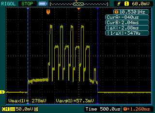
The consumption peaks to 27.8mA (but averaging that over the transmission period will give you roughlty 12mA as the datasheet states). The 4 bytes payload (unsigned long) take 2.88ms to transmit, that includes the overhead. I will still have to experiment with slower/higher data rates and how that affects range.
Hi Martin,
Nice example using the nrf24l01.
I could test it on a breadboard atmega328 @ 16MHZ and 3.0V, and I got 0.87 mA during sleep and 1.1 mA during transmission.
I’d like to ask you if you already tried to wake the nrf24l01 using the IRQ signal after put every body to sleep (transceiver and microcontroller) using mirf lib.
I’m facing this issue, after set nrf24l01 to power down mode, I could be able to detect the signal from incoming message (if I don’t put the transceiver to sleep, I could detect IRQ signal with no problems and wake MCU !!! =D).
Regards!
Gavazza
Hi Gavazza,
as datasheet says, NRF can’t rcv anything during power down, thus it will never let the IRQ pin active,(nothing received during power down)
regard
davids
Hi David,
Thanks for your reply, since I read that in sleep mode it kept the SPI registers active, I though that I could try to receive and access the register to verify for a new incoming message.
I believe I could use the nrf24L01+ in standby I mode (something around 22-25 uA). BUT ….. on my last configuration tests I couldn’t get this low current measure :(. The set (atmega328 internal 8mhz + nrf24l01+) is consuming 1.5 mA (atmega in power down) and 0.85 mA (both atmega and NRF in power down).
If I remove NRF from the circuit, my arduino is consuming just 0.001mA during sleep mode (power down mode + ADC off + brown-out off) if I connect the NRF the current consumption grows drastically.
David, have you already measured the consumption (just using an atmega328p-pu + nrf24l01+)? If possible i’d like to check/compare these values.
regards
gavazza