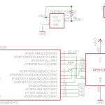
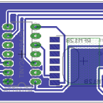
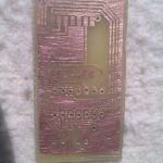
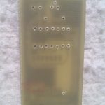
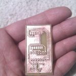
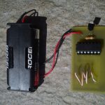
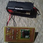
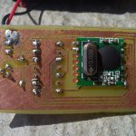
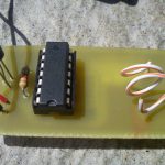
Following the fiasco with the first version of the PCB, I have decided to create a single sided PCB so that the DIP socket that was causing me trouble is on the top. Here are the results, the PCB works great and the temperature is being sent every 60 seconds using the DS18B20 sketch.


Great work, very helpful ! Does your sketch work with ATtiny 85 ?
You will have to modify the pins, PB3 and PB4 seem ideal candidates for powering up the DS18B20 and one-wire bus. In fact, using ATtiny84 for this project is a bit of overkill. I will get one ATtiny85 and create another sensor board when I have time.
Thanks ! So
#define ONE_WIRE_BUS 3
#define tempPower 4
would do the job ?
Yes
Thank you !
On Second thought, it may not be so easy. Given that the ATTiny has only 8 pins, 3 of them are for GND, VCC and RESET,so you are left with 5 but the RFM12B uses SPI so that consumes up another 3 plus one for the chip select so you are left with only one pin.. a hack may be to use that left pin for one wire bus and then use the DS18B20 in parasite mode, but I haven’t tried that
Actually, I’m not using RFM12B module but very cheap RF link which use only one data pin with a Manchester library for encoding/decoding. So it should normally fit 🙂